
Owner's manual


Page 76
K5 System Technical Guide
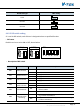
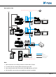
4.4.2.6§Examples:
Work with C5-F4
C5-F4
C5-F4
1
2
3
4
1R 2W
GD VD T/R+ T/R- Z1 Z2 Z3 Z4 COM COM PR
3Y
4B
FV+FV- P- AU P- P+ P+D1&D2
C5-AT27
PS5
1 2 3
654
7 8 9
#0
*
RF CARD
CN1
CN2
CN-LK
J/KMB JP-LK
Bus
EB+
EB-
N.O
LK+
LK-
+12V
12
3
T/R- T/R+
1 2
3
P+ P- P+ P- RS485
SW1
JWB(IN) JWB(OUT) CN(MDS) ETHERNET
PA
VR600
+
S1
POWER
LINK
IN-USE
AG
1
ON DIP
2 3 4 5 6
1 2
3
P+
P-
P+ P- RS485
SW1
JWB(IN) JWB(OUT) CN(MDS) ETHERNET
C5-IPC
IP-MR18
AC
+
-
+
-
+
-
To other monitors
PS5
AC
+
-
+
-
C5-F4
C5-F4
1
2
3
4
1R 2W
GD VD T/R+ T/R- Z1 Z2 Z3 Z4 COM COM PR
3Y
4B
FV+FV- P- AU P- P+ P+D1&D2
C5-AT27
To other monitors
+
-
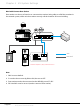
To Next C5-F4
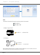
F4/F4DV/F4Q
ON DIP
Keep 3 jumpers
LAN
Note that VD-SET must be set to 120 if the C5-F4 is the last one of the bus
HI
120
HI
120
HI
120
Note that ID Code(#8001-1) setting in MR18 must be set to 1
CAT5
RVV2*1.0mm2
Note:
1. SW1 need to be set to F4 position to match with C5-F4.
2. S1 need to be set correctly, all to OFF.
3. Door station need to be connected to the JWB (IN) port of C5-IPC.
4. DS Serial NO. must not be set to 0(while 0 to be the controller)
Chapter 4 K5 System Settings