
Owner's manual


Page 32
K5 System Technical Guide
•
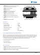
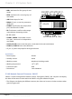
LED1:
Indicators for rst group of card
reader
•
LED2:
Indicators for second group of
card reader
•
JWP:
Power input, DC 24V
•
RS485:
PC port, to set the parameters
of GP-LIFT
•
CN-NET:
Signal input and output, RJ45
port, connected to C5-MDS
•
PA:
Test button, used for card manage-
ment without connecting to LAN
•
S1:
DIP switch
•
CN-RD1, CN-RD2:
Card reader connec-
tion port, connected to independent
card reader
•
CN-LK1, CN-LK2:
Lock connection port, connected to lock and outlet button
•
CN-DSI-1, CN-DSI-2:
Door status detection
• JP_LK1, JP_LK2: Lock jumper for lock type selection
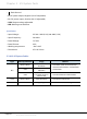
Specication
• Power supply: DC24V
• Standby current: 50mA
• Working current: 90mA(not including reader)
• Working temperature: -10
0
C~40
0
C
• Connection port: RJ45
• Dimensions: 140*150*60mm
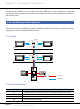
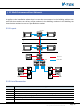
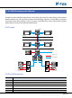
2.3.4.8§Network§Camera§IP§Converter:§CM-IPC
CM-IPC is a device designed for Network camera. Through the CM-IPC, the computer can display
the video of the camera connected to the CM-IPC using the software IP-Agent.
• The IP-Agent can display the different cameras; the video can be sent to indoor monitors when
guard Ip-agent calls
GP-ACS
JP-LK1 CN-DS1-1 CN-LK1
CN-LK2
CN-RD1
CN-RD2 LED2
LED1 S1
CN-DS1-2JP-LK2
JWP JWB
POWER
LINK IN-USE PA CN-NET
RS485
1
ON DIP
2 3 4 5 6
P+ A1 P- D1 D2 JWB(IN) JWB(OUT)
P-
JP-LK1
JP-LK2
S1
SN-
SN+
P+
P-
POWER LINK IN-USE
PA
RS485
1
2
3
1
2
3
EB+
EB-
N.O
LK+
LK-
+12V
BEEP
LED
LED2
LED1
WG1
WG0
P-
+12V
Chapter 2 K5 System Parts