
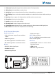
Owner's manual

Page 30
K5 System Technical Guide
•
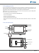
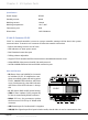
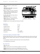
JWP:
Power input. P+, positive 24V; P-,
negative.
•
JWB (IN1, IN2, IN3, IN4):
Connected to
door stations (Max.4).
•
PA:
Test button. Press PA, the IN-USE
indicator will light, and then start to
monitor door station connected circu-
lar with click of relay.
•
S1:
DIP Switch function setting, refer to
DIP switch setting.
•
SW1:
Always set to the 2V, 2A position.
•
JTAG:
update port. Connected to PC to
update the rmware of C5-MDS
•
RS-485:
PC port. Used to update the rmware of C5-MDS.
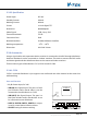
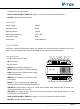
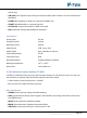
Specication
• Power input: DC 24V
• Standby Current: 50mA
• Working Current: 80mA
• Connection Port: RJ45
• Working temperature: -10
0
C ~ +40
0
C
• Dimension: 140*150*60 mm
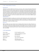
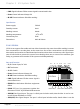
2.3.4.6§Picture§Memory§Controller:§C5-IMC
C5-ICM is independent picture memory controller for K5 system. When visitor call the monitor, the
C5-IMC will start to capture picture and save it, the resident can view the picture on the indoor
monitor.
• Picture playing is continuous and the switch time can be set by DIP switch
• Up to 800 pictures can be saved
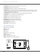
Parts and functions
•
S201:
DIP switch
•
PA201:
Capture picture in normal status, for DIP test in test status
•
PA202:
Play picture in normal status, for EEPROM test in test status
•
PA203:
Exit in normal status, for monitor communication in test status
C5-MDS
JWB(IN4)
P-
P+
P-
P+
PA
S1
1
ON DIP
2 3 4 5 6
JWB(IN3) JWB(IN2) JWB(IN1) JWB(OUT)
JWB(OUT)
T/R-
ERROR
INUSE
LINK
POWER
T/R+
JWP PA S1
ERROR
IN-USE
LINK
POWER
RS-485
JWB(IN4) JWB(IN3) JWB(IN2) JWB(IN1)
Chapter 2 K5 System Parts