
Owner's manual

Page 28
K5 System Technical Guide
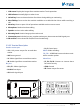
Specications
Power supply: DC24V
Standby current: 60mA
Working current: 120mA
Working temperature: -10
0
C~40
0
C
Connection port: RJ45
Dimensions: 140*150*60mm
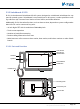
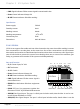
2.3.4.4§IP§Converter:§C5-IPC
C5-IPC is a network controller. It serves as system controller, manages all the data in the system
communication. To severs as a IP converter to effect the network connection.
• Built-in watchdog circuit in case of crash
• LED Indicators to show system status
• RJ45 Standard connection port
• Talking volume adjustable
• Support TCP/IP network and ber transmission or broadband network access
• Adopt MPEG4 video protocol and G.729 audio protocol
• Include 100Mbit Ethernet LAN and RS485 connection port
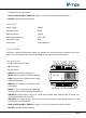
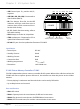
Parts and Functions
•
PA:
Reset. Press and hold PA for 3 seconds
to initialize C5-IPC; If initialization com-
plete successfully, power off, and re-power
C5-IPC, LINK&IN-USE indicators will icker
once simultaneously, then INK indicator
will flicker till IN-USE indicator is always
ON
•
S1:
DIP Switch. Refer to DIP Switch Setting
•
JTAG:
PC Port. Update C5-IPC program by
PC that is connected by RS232 convertor
•
RS485:
PC Port. Set parameters update
the firmware of C5-IPC by PC RS485-USB
convertor
•
JWP:
Power Input P+: Positive,24V; P-: Negative
•
JWB (IN):
Bus Signal Input. RJ45 port includes audio, data & video. It can be connected to door
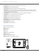
1 2
3
P+ P- P+ P- RS485
SW1
JWB(IN) JWB(OUT) CN(MDS) ETHERNET
PA
VR600
+
S1
POWER
LINK
IN-USE
AG
1
ON DIP
2 3 4 5 6
C5-IPC
JTAG S1 POWER PA VR600
IN-USELINK
JWP
RS-485 JWB(IN) CN-MDS
CN-NETJWB(OUT)SW1JP1/2/3
Chapter 2 K5 System Parts