
Owner's manual

Page 26
K5 System Technical Guide
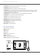
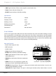
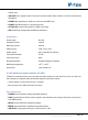
•
LINK:
Signal indicator. Flicker means signal is transmitted in bus
•
Power:
Power indicator. Always ON
•
IN-USE:
Status Indicator. ON while working
Specications
Power supply: DC24V
Standby current: 8mA
Working current: 80mA
Working temperature: -10
0
C~40
0
C
Connection port: RJ45
Dimensions: 88*140*32mm
2.3.4.2§C5-F414
C5-F414 can support four audio and one video channels at the same time while working. It means
four conversations can take place at the same time. One of the conversations can be between
door station and monitor or Switchboard and monitor; other three are intercom calls. Signal sepa-
rator is built inside to protect the system from shutting when one or some of the monitors gets
faulty, to guarantee each monitor in the system work independently.
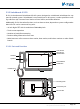
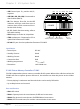
Parts and Functions
•
P+, P-:
Power input, DC 24V
•
PA:
Test button
•
S1:
DIP Switch
•
Power:
Power indicator. Always ON
•
IN-USE:
Status Indicator. ON while working
•
LINK:
Signal indicator. Flicker means signal is
transmitted in bus
•
ERROR:
Error indication. ON when equipment
failure
•
RS485:
PC Port. Set parameters update the
rmware of C5-IPC by PC RS485-USB convertor
•
JWB (IN):
Bus Signal Input. The port is a RJ45 port includes audio, data & video. It can be con-
nected to last distributor or C5-IPC
•
JWB (OUT):
Bus Signal Output. The port is a RJ45 port includes audio, data & video. It can be
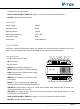
PORT-A
PORT-A
PORT-B PORT-C PORT-D JWB(IN) JWB(OUT)
VD-SET(L=HIGH)
P-
P+
P-
P+ P- PA
P+
PA
S1
1
ON
2
T/R-
ERROR
INUSE
LINK
POWER
T/R+
C5-F414
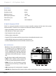
PORT-B PORT-C PORT-D JWB(IN) JWB(OUT)
VD-SET
S1
IN-USE LINK RS485
POWERERROR
Chapter 2 K5 System Parts