
Owner's manual

Page 24
K5 System Technical Guide
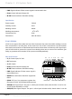
1.
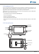
LCD screen:
Display the icon menu and images ,touch operation
2.
Microphone:
Receives sound from the user
3.
Alarm Button:
Blink when the guard unit receives alarm record
4.
LED Indicator:
(1) Red indicator ash rst, green indicator ash later when power on; (2) Blue
indicator normally on when work in normal; (3) Blue indicator ash when in calling state; (4)
Red indicator ash when in talking state
5.
Unlock Button:
Press to release the door for visitors during talking or monitoring
6.
Call Button:
Press to activate the intercom function page
7.
Handset:
Pick up to talk with the visitors or users
8.
Speaker:
Output sound from the visitors or users
9.
Handset Line:
Connect guard unit with handset.
10.
Mounting hook:
Used to hang up the monitor unit
11.
Connection port:
Bus terminal
12.
SD card slot:
Use to insert SD card
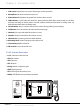
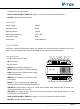
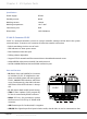
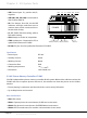
2.3.3.2§Terminal§Descripon
•
L1,L2:
Connect to the bus line
•
SW1:
DIP switch
•
SW+:
Reserve
•
SW-:
Reserve
•
Exring:
Buzzer connection port
•
GND:
Signal ground
•
VD:
Video signal connection port
•
RS485:
USB-RS485 communication terminal
1 2 3 4 5 6
ON
DIPS
SW-
SW+
EXring
GND
VD
RS485
L1
L2
1 2 3 4 5 6
ON
DIPS
SW-
SW+
EXring
GND
VD
RS485
L1
L2
Chapter 2 K5 System Parts