
Owner's manual

Page 18
K5 System Technical Guide
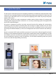
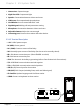
1.
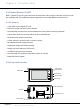
Camera Lens:
Capture images
2.
Night View LED:
Compensate light
3.
Speaker:
Conversation between visitors and users
4.
LCD Screen:
Show operational tips and others
5.
Card Window:
Access control with ID/IC card
6.
Digital Keypad:
Making call and parameters setting
7.
Microphone:
Conversation between visitors and users
8.
Adjustable Camera:
Adjust the camera angle
9.
Connecting port:
Connect door station with other devices
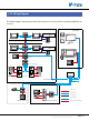
2.3.1.3§Terminal§Descripon
•
+12V:
12VDC power output
•
LK-(GND):
Power ground
•
LK+ (COM):
Common contact of the Relay
•
NO.:
Normally open contact of the Relay (Can be set to be normally closed)
•
EB+:
Exit button connection port. (Short EB+&EB- to unlock)
•
EB-:
Exit button connection port
•
JP-LK:
For electronic lock safety type setting (refer to Door Station Lock Connections)
•
T/R-:
USB-RS485 communication terminal negative
•
T/R+:
USB-RS485 communication terminal positive
•
JWP (P+, P-):
Power input for door station
•
JWB (OUT):
BUS Output (Including Data, audio and video signal)
•
SD Card Slot:
Update language and UI of door station
•
J/KMB:
Connect to keyboard on door station.
SD Card Slot
12
3
CN1 CN2
CN-LK
J/KMB JP-LK
EB+
EB-
N.O
LK+
LK-
+12V
12
3
T/R- T/R+
Chapter 2 K5 System Parts