
Owner's manual
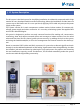

Page 15
K5 System Technical Guide
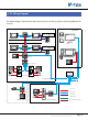
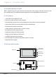
§§ 2.1§Wiring§Diagram
The below diagram demonstrates what the K5 system can do, by all the connecting different de-
vices up.
C5-MDS
1 2 3
654
7 8 9
#0
*
RF CARD
PS5
PS5
PS5
C5-IPC
1 2 3
654
7 8 9
#0
*
RF CARD
C5-F414
1
2
3
4
1
2
3
4
PS5
PS5
RF CARD
1 2 3
4 5 6
7 8 9
*
0 #
C5-IPC
CM-IPC
C5-F414
1
2
3
4
1
2
3
4
Network Switch
PS5
Common Door Station
Residential Building
Floor 1
Exit Button
Exit Button
Exit Button
Floor N
4 Alarm Zones
Secondary Door Station
Multi-Door Station Switch
Unit Door Station
IP Converter
IP Converter
Distributor
Indoor Monitor
4 Alarm Zones
Network Camera
To Next Network
Switch or LAN/WAN
Switchboard: IP-G21
IP-Agent
Switchboard
SOS
RVV 2*1.0
CAT5 Cable
RVVP 4*0.5
Coaxial-cable
RVV 2*1.0(for each zone)