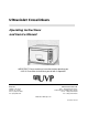
Ultraviolet Crosslinkers Operating Instructions and Service Manual IMPORTANT: Please read these instructions before operating your UVP UV Crosslinker to familiarize yourself with its operation. UVP, LLC 2066 W. 11th Street Upland, CA 91786 Phone: (800) 452-6788 Fax: (909) 946-3597 Ultra-Violet Products Ltd. Unit 1, Trinity Hall Farm Estate, Nuffield Road, Cambridge CB4 1TG UK Phone: +44(0)1223-420022 Fax: +44(0)1223-420561 Web Site: www.uvp.
UV CROSSLINKERS UVP CONTENTS Introduction 3 Important Safety Information 3 Description and Specifications 3 Operation 4 Applications 7 Maintenance, Care and Cleaning 7 Changing the UV Wavelength 8 Calibration Procedure 9 Replacement Parts 10 General Servicing Procedures 11 Schematic Diagram 15 Technical Support 16 Warranty 16 2
UV CROSSLINKERS UVP INTRODUCTION UVP Crosslinkers offer researchers an instrument to quickly, safely and efficiently expose samples to a controlled amount of ultraviolet radiation. CL-1000 series features a lay-down type drawer while the CX2000 has a pull out drawer. Exposure of samples to UV provides for the following: • • • • • • • Crosslinking of DNA or RNA to nitrocellulose, nylon or reinforced nitrocellulose. PCR sample contamination control.
UV CROSSLINKERS • • • • • • • • UVP Internal safety interlock Large LCD readout Tactile membrane switch keypad UV blocking viewing window Large interior UV exposure chamber Dual safety fused Removable power cord Laydown type door – CL-1000 series; pull-out drawer – CX-2000 Electrical Part No. Nominal Voltage/Hertz/Amp CL-1000 Shortwave Crosslinker 95-0174-01 115V/60Hz/0.7A 95-0174-02 230V/50Hz./0.7A 95-0174-03 100V/50-60Hz/0.8A CL-1000L Longwave Crosslinker 95-0228-01 115V/60Hz/0.
UV CROSSLINKERS UVP The UV Crosslinker can be operated on the following settings: A. Preset UV Energy Exposure Setting: Push the PRESET and then ENERGY on the tactile touch pad. The red light at each position should now be lit and the preprogrammed UV exposure setting of 120,000 microjoules per cm² is displayed in the LCD as 1200. Note: THE LCD DISPLAYS 1200. THIS MUST BE MULTIPLIED BY 100 TO OBTAIN EXPOSURE. Push START. After a slight delay to energize the UV tubes, the LCD will begin to count down.
UV CROSSLINKERS C. UVP User-Defined UV Energy Exposure Setting: Sometimes it may be necessary for you to set your own standards for exposure. This is easily accomplished as follows: Push the ENERGY on the tactile touch pad then set your energy exposure requirements by pushing the numbers on the touch pad. The energy exposure settings should now be displayed on the LCD in flashing mode. Note: YOUR ENERGY EXPOSURE SETTINGS DISPLAYED MUST BE MULTIPLIED BY 100.
UV CROSSLINKERS UVP APPLICATIONS The Crosslinker is a multi-purpose ultraviolet exposure instrument for use in the laboratory. A wide variety of applications for ultraviolet radiation exist in the laboratory. A. UV crosslinking of DNA and RNA by covalently binding nucleic acids to transfer membranes nitrocellulose, nylon or nylon-reinforced nitrocellulose membranes after Northern, Southern, slot or dot blotting.
UV CROSSLINKERS UVP CHANGING THE UV WAVELENGTH A UV Crosslinker is purchased with shortwave, longwave or midrange tubes. However, if user requirements and applications change, the Crosslinkers provide you with the unique ability to change the ultraviolet wavelength and recalibrate the UV sensor and microprocessor to the new UV wavelength. This is accomplished by purchasing FIVE tubes of the NEW UV wavelength and the proper UVP calibration sensor.
UV CROSSLINKERS UVP CROSSLINKER CALIBRATION PROCEDURE Equipment necessary: • • • • • Chart recorder Two probes with banana plug adapters One radiometer with UVX-25 calibrated sensor Cable with banana plug and jack adaptor to connect radiometer to chart-recorder Power source (100V, 115V or 230V) Procedure: 1. Connect the Crosslinker to the power source. Do not turn on the unit at this time. 2.
UV CROSSLINKERS UVP 2 14. Set the radiometer scale to 20mW/cm . 15. Connect the radiometer to PEN 2 of the chart recorder. 16. Select 1V scale for PEN 2 and a speed of 60mm/min. 17. Lower both pens, turn the CHART DRIVE switch on, change the pens' switches to MEASURE position and adjust for zero level. 18. Select an energy level of 600 Joules on the Crosslinker and press the START button. 19. When the cycle is completed, repeat for 1,200 and 2,000 Joules levels. 20.
UV CROSSLINKERS UVP GENERAL SERVICING PROCEDURES A. Operations without Removing the Top Cover Changing the tubes It is recommended to change all FIVE 8-Watt 254nm UV tubes at the same time. The unit does not require recalibration if you are replacing the old sources with new sources of the same wavelength. B. 1. Purchase five tubes from UVP. 2. Unplug the unit from the electrical supply. 3.
UV CROSSLINKERS UVP Note: If more than one tube holder is to be replaced, the wiring schematic diagram may be of assistance. Replacement of starters 1. Locate the starter to be changed. These are positioned in a vertical row on the right hand side of the internal chassis assembly. 2. Turn starter(s) 30 degrees anti-clockwise and then pull out of the holder. 3. Reverse above procedure with recommended starter. Replacement of starter holder 1. Locate the starter holder to be changed.
UV CROSSLINKERS UVP 3. Release main connector by holding the nuts with a spanner and then on the outside back of the unit, release the two screws one at a time (using a screwdriver). The main connector should now be loose. 4. To replace, reverse the above procedure. Replacement of main switch This is located on the front panel below the membrane pad. 1. Remove the wires noting their position. 2. Remove the switch by pushing it out from the back towards the rear of the front panel. 3.
UV CROSSLINKERS UVP C. Operations with the Internal Chassis Assembly Removed Removal of the assembly 1. Release the wire to the micro switch located on the bottom left internal chassis assembly. 2. Release the main power cable to ballasts - black wire with connector (color red). 3. Release all eight nuts positioned four on top of the unit, two sets on either side of the unit. See diagram for positions. 4. Slide unit out from the main frame.
UV CROSSLINKERS UVP Changing plastic feet The feet are fitted to the bottom of the cabinet. They are removed by unscrewing the screw mounted inside each foot.
UV CROSSLINKERS UVP TECHNICAL SUPPORT UVP offers technical support on all of its products. If you have any questions about the product’s use, operation or repair, please contact our offices at the locations below. Note: A Returned Goods Authorization (RGA) number must be obtained from UVP Customer Service before returning any product.