BioSpectrum® Imaging System™ Instruction Guide ______________________________________________________________________________ UVP, LLC 2066 W. 11th Street, Upland, CA 91786 Tel: (909) 946-3197 / (800) 452-6788 Fax: (909) 946-3597 Ultra-Violet Products Ltd. Unit 1, Trinity Hall Farm Estate Nuffield Road, Cambridge CB4 1TG UK Tel: +44(0)1223-420022 Fax: +44(0)1223-420561 Web Site: www.uvp.
BioSpectrum Imaging System 2 Table of Contents Introduction ..................................................................................................................................................................3 Components .................................................................................................................................................................4 Darkroom Cabinet ...............................................................................................
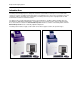
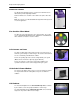
BioSpectrum Imaging System Introduction The BioSpectrum Imaging System is designed to automate research with one-touch preset or user-defined PC controls for accurate, repeatable imaging and analysis of chemiluminescence, fluorescence, bioluminescence and colorimetric samples (depending upon configuration). The BioSpectrum incorporates a light-tight darkroom with VisionWorksLS software for automated control.
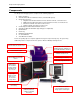
BioSpectrum Imaging System 4 Components The BioSpectrum Imaging System is comprised of the following equipment: Darkroom Cabinet Automated Filter Wheel and Emission Filters (3 Included with System) CCD Camera and Lens: o MegaCam 810 with either 50mm f/1.2 Fixed, 30mm f/1.4 Fixed, or f/2.8 Zoom Lens o OptiChemi™ 610 with either 50mm f/1.2 Fixed, 30mm f/1.4 Fixed, or f/2.8 Zoom Lens o BioChemi™ 510 with 12.5-75mm f/1.2 Zoom Lens o GelCam 310 with 12.5-75mm f/1.
BioSpectrum Imaging System Darkroom Cabinet The BioSpectrum Imaging System is constructed of aluminum and is fabricated to provide a light-tight chamber. Darkroom Dimensions: 17.5W x 17.5D x 32H inches (445 x 445 x 813 mm) Note: The camera cover will add additional height which will vary based on camera application. Five Position Filter Wheel The filter wheel accommodates up to five emission filters. The system comes standard with Ethidium Bromide, SYBR Green and SYBR Gold filters.
BioSpectrum Imaging System Epi Illumination Standard overhead lighting includes 365nm UV, Visi-Blue 480nm and white light. Lighting is controlled via the software interface. NOTE: The BioSpectrum includes an interlock switch that turns off all UV illumination, including the epi 365nm UV, when the darkroom door is opened. Be sure the darkroom door is completely closed for proper UV operation.
BioSpectrum Imaging System 7 VisionWorks®LS Software VisionWorksLS software controls the darkroom functions and lighting as well as the motorized lens and camera. The system may be configured with VisionWorksLS analysis software for analysis of gels, plates, blots and other samples. BioLite Access Ports Additional optional equipment can be added to the BioSpectrum Imaging System through the side access ports.
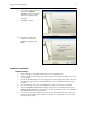
BioSpectrum Imaging System Installation Installing VisionWorksLS Software 1. Insert the VisionWorksLS CD (not network CD) into the computer. 2. Click on the Install button for VisionWorksLS. 3. Click OK, Next, agree to “I accept terms of licensing agreement”, then Next. Leave all options in their default settings. Then click Next, Next, Install and finally Finish. Registering the Software Open the Software 1. Double click the VisionWorksLS software icon on the desktop. 2.
BioSpectrum Imaging System 8. If the computer is not connected to the Internet, click Offline activation to register the software. This allows the user to obtain the activation code and enter it at another time. 9. Click Next to continue. 9 10. Click the link provided and complete the form to obtain registration instructions. Click Finish. Hardware Installation Darkroom Setup 1. Remove all the tape on the darkroom (filter wheel, doors and interior cables). 2.
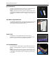
BioSpectrum Imaging System 10 Darkroom Filter Setup 1. Ensure that the darkroom is in a fixed and permanent location as filters may slide in movement. 2. Locate the filter wheel in the darkroom’s camera well at the top of the darkroom, accessible when the camera and lens are removed. 3. Using your fingers, manually rotate the filter wheel to the appropriate filter location. Each filter location in the darkroom is numbered for a corresponding filter.
BioSpectrum Imaging System 11 Zoom Lens Controller Setup UVP Lens Controller (pictured without camera and lens) Assemble the lens controller’s connective devices as follows: 1. Ensure that the zoom lens controller components and connections are assembled per the picture at right. 2. Plug the power cable into the power supply. 3. Plug the other end of the power cable into an electrical outlet. 4. Wait until VisionWorksLS software is loaded to plug the USB cable into the computer.
BioSpectrum Imaging System 12 Connecting to a PC and Powering Up the System 1. Connect the USB cable from the computer to the rear exterior of the darkroom. 2. Connect the camera to the computer and darkroom per the camera instructions in the back of this manual. Ensure that the camera is connected to its own dedicated USB port and not to a USB hub or other similar shared device. 3.
BioSpectrum Imaging System 13 Camera Installation High sensitivity, scientific grade CCD cameras are designed for use with UVP’s BioSpectrum Imaging Systems. This section covers the components and steps required to install and operate UVP’s cameras. Each camera has slightly different installation instructions, and the following cameras are covered in this manual: GelCam 310 BioChemi 510 OptiChemi 610 MegaCam 810 Refer to the packing list for the camera included with your specific system.
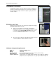
BioSpectrum Imaging System 14 Hardware Installation 1. Slide the camera and lens assembly into the camera base. The base comes installed to the darkroom from the UVP factory. 2. Plug the serial cable from the motorized lens into the darkroom. 3. Plug the 90 degree USB cable into the top of the camera. Leave the other end unplugged until ready to install the VisionWorksLS CD. 90 degree USB cable Serial connection for motorized lens NOTE: Camera may be a different color or size than shown. 4.
BioSpectrum Imaging System 15 Software Installation Install the Camera Driver 1. Plug in the 90 degree USB cable from the camera into the USB port. Ensure that the camera is connected to its own dedicated USB port and not to a USB hub or other similar shared device. 2. The computer should display Found New Hardware. Click Yes, Next, Install from a list, Next, Don’t search, Next, double click on Show all Devices, click Have disk, and then Browse. 3.
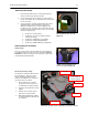
BioSpectrum Imaging System 16 Hardware Installation The photograph shows the parts required for assembly of the MegaCam 810 and BioChemi 510 camera kits with the motorized lens on the BioSpectrum Imaging System. The OptiChemi 610 camera will have a different appearance but will be installed in the same manner. Note: The image above shows the 50mm f/1.2 lens (6). Another lens and/or lens controller may be shipped with the system. 1.
BioSpectrum Imaging System 17 Operation Using the System Caution: In BioSpectrum systems equipped with a motorized lift platform, do not place objects under the platform as these items will suffer damage if lift platform is moved to the lowest position. Note: The motorized lift platform (if equipped) is only functional if the darkroom door is closed. Turn on the darkroom power switch, located on the upper right side of the darkroom, prior to opening the software.
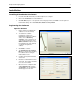
BioSpectrum Imaging System Camera Control The camera is controlled via VisionWorksLS software by clicking on the Acquisition Action Tab and then clicking on the Camera Menu Button. (Cameras have different functionality. Some options listed to the right in the Camera Menu may not appear for each camera. VisionWorksLS software automatically detects and enables the built-in functionality for each camera.
BioSpectrum Imaging System 19 Adjusting the Lift Platform Height BioSpectrum with Automated Lift Platform When using the Automated BioSpectrum, the lift platform height is adjusted from the Tray Height section of the Lighting Menu in VisionWorksLS. The lift platform adjusts to any location within a ten-inch travel range. When adjusting the lift platform for experiments, the software continuously tracks the position.
BioSpectrum Imaging System 20 Capturing Images Focusing the Lens Using Image Preview 1. Place the sample or focus target on the surface where the sample will be imaged. 2. Turn on the darkroom white light. 3. Start the image preview by clicking on the Preview button within VisionWorksLS and move the sample around as necessary. 4. Set the aperture to the lowest setting (lowest f-stop number) and adjust the exposure time to see the target clearly. 5.
BioSpectrum Imaging System 21 Service Procedures Return Procedure A Returned Goods Authorization (RGA) number must be obtained from UVP Customer Service before returning any product. Troubleshooting No Power to the Darkroom 1. Recheck main power cord connections to the darkroom. 2. Check fuses, located at the back of the unit, near the power port. A flat-head screwdriver will be required. Turn the fuseholder cap counterclockwise and the fuse holder will pop out.
BioSpectrum Imaging System 22 Contact UVP for information on the BioLite MultiSpectral Light Source for directed epi or transillumination fiber optic lighting with filters for excitation of fluorescent multiplexed Western blots, NIR, DIGE 2D gels, PAGE gels, microplates and more. Technical Support UVP offers expert technical support on all UVP products If there are any questions about product use, operation or repair, contact UVP’s offices at the locations below.