
User Manual
27
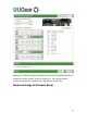
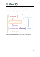
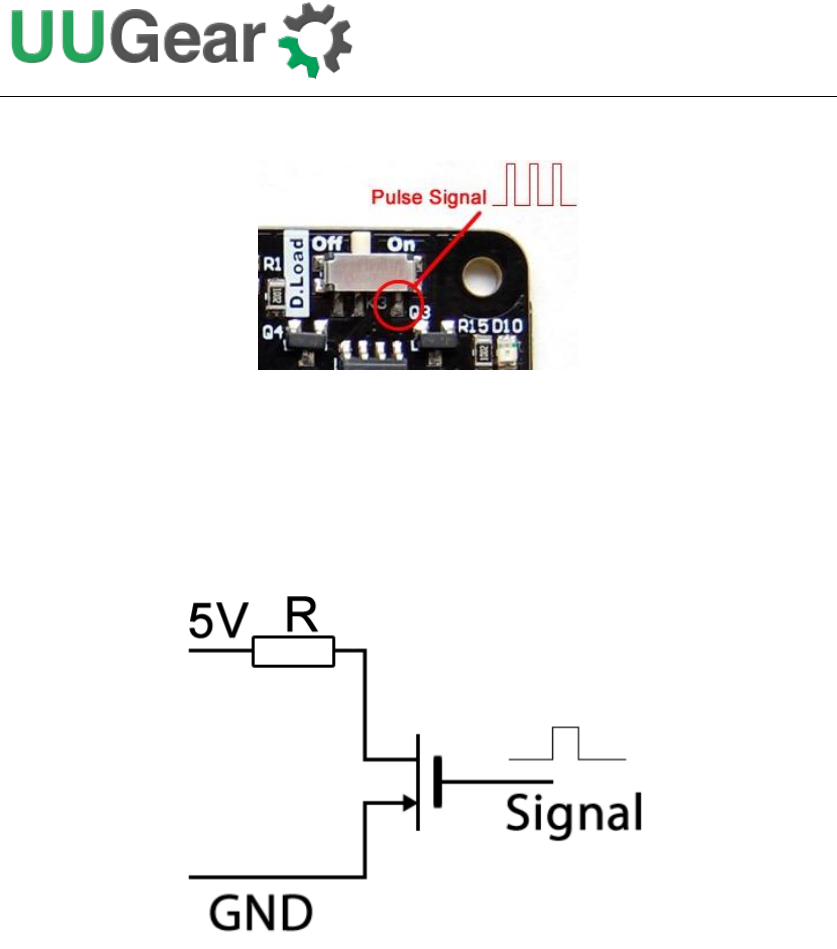
the right lead of the switch K3, as shown below:
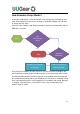
By default, the dummy load is off. If you turn the switch to the right side, the pulsing
signal will be connected to a MOSFET, and controls the on/off of load (R20).
When dummy load switch is on, the pulsing signal connects to the gate of a
N-MOSFET. When the signal goes high, the MOSFET is conducted and the current
will be consumed (via the resistor R20).
The peak current can be calculated with this formula:
I
max
= V
cc
/ (R + R
ds
)
Where Vcc is 5V, R is the load resistor (R20) and R
ds
is the resister between the drain
and source of the N-MOSFET, which is a few Ohms.
Some power banks have relatively complex algorism to decide whether they should
cut off the power. Some of them even calculate the integration of current to make sure
certain current should be consumed when the power is on. For those power banks,
this “pulsing dummy load” trick may not work well. In this case you might want to use a
simple resistor to be a real load to drain enough current and keep the power bank
alive.