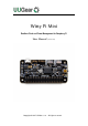
Witty Pi Mini Realtime Clock and Power Management for Raspberry Pi User Manual (revision 1.01) Copyright © 2017 UUGear s.r.o. All rights reserved.
Table of Content What is Witty Pi (Mini)? ...................................................................................... 1 What is in the Package?..................................................................................... 2 Witty Pi Mini Specifications................................................................................. 4 Before Installation .............................................................................................. 5 Software Installation ...................
GND .......................................................................................................... 30 LED ........................................................................................................... 30 Vbat .......................................................................................................... 31 INT ............................................................................................................ 31 Vout ...............................................
What is Witty Pi (Mini)? Witty Pi is small extension board that can add realtime clock and power management to your Raspberry Pi. After installing Witty Pi on your Raspberry Pi, you get some amazing new features: Gracefully turn on/off Raspberry Pi with single tap on the switch. Fully cuts power for Raspberry Pi and all its USB peripherals after shutdown. Raspberry Pi knows the correct time, even without accessing the Internet. You can schedule the startup/shutdown of your Raspberry Pi.
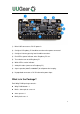
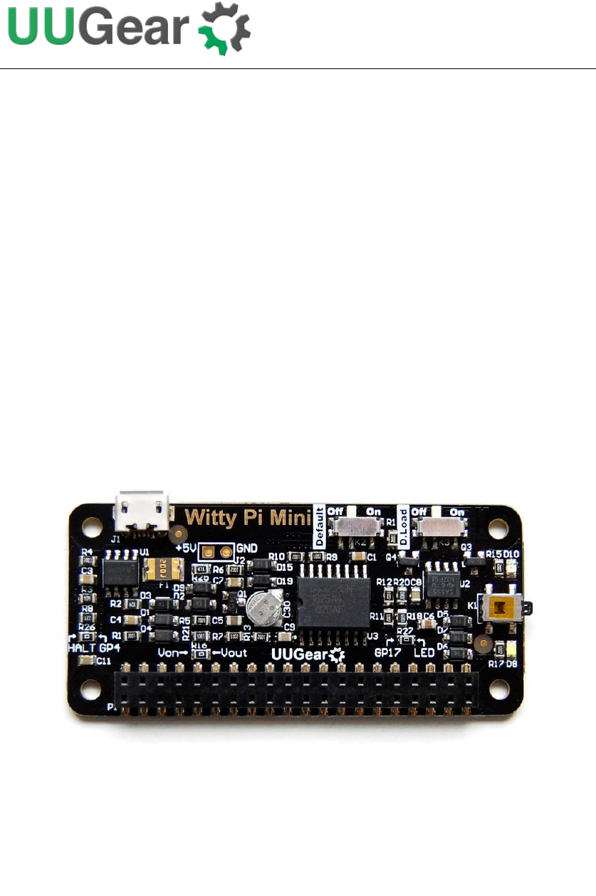
1) Micro USB connector as DC 5V power in 2) Configure if Raspberry Pi should be turned on when power connected 3) Configure if dummy pausing load should be turned on. 4) Red LED as power indicator, when Raspberry Pi is on. 5) Tact switch to turn on/off Raspberry Pi. 6) White LED as action indicator. 7) 2x20-pin header (connects to Raspberry Pi). 8) Super capacitor (0.08F, or 80000uF) for off-power time keeping. 9) Unpopulated connector as DC 5V alternative power input.
3
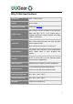
Witty Pi Mini Specifications Dimension: 65mm x 30mm x 4mm Weight 9g (net weight) Realtime Clock Chip DS3231SN (datasheet) Red LED: lights up when Raspberry Pi gets powered. LED Indicator Connector White LED: lights up for a few seconds when a shutdown command is received, or blinks when Witty Pi Mini is standing by. 20x2 surface-mounted header with 2.54 mm pitch and 2mm plastic height. Micro USB female connector as 5V DC input. Time Keeping Using 0.08F super capacitor as time keeping power source.
Before Installation If you have installed Raspbian Jessie by directly flash the OS image into SD card, you can skip reading this section. You will need to installed the OS on the SD card first. We recommend NOT to use NOOBS, instead download the Raspbian image and directly flash it into your SD card (tutorial is here). The process could be faster and you will not have the problem caused by the NOOBS boot menu (read on for details).
Software Installation We strongly recommend to install the software for Witty Pi Mini BEFORE physically mount Witty Pi Mini on your Raspberry Pi. Witty Pi Mini uses the same software with Witty Pi 2. You will need to have your Raspberry Pi connected to the Internet. The installation will be very simple if you run our installing script. The wiringPi utility is required by the software so the script will install it for you, if you don’t have it installed yet.
The Qt 5 installation is for the GUI only. If you don’t plan to use it, you can skip this step for now, as Qt 5 installation will take a while. You can also manually install these packages and make those configurations, if you prefer to. After the installation, please remember to reboot your Raspberry Pi, so the Realtime clock I2C hardware will be loaded correctly. You will see a new “wittyPi” directory, and it contains 5 runnable files: pi@raspberrypi ~ $ cd wittyPi pi@raspberrypi ~ /wittyPi $ ls daemon.
Now the software has been installed, and you will need to physically mount Witty Pi Mini on your Raspberry Pi. Software Update/Uninstallation If you want to update the software to newer version, you don’t have to uninstall it first. Just remove or rename your “wittyPi” directory and repeat the installing process, then you are all set. pi@raspberrypi ~ $ mv wittyPi wittyPi.bak pi@raspberrypi ~ $ wget http://www.uugear.com/repo/WittyPi2/installWittyPi.sh pi@raspberrypi ~ $ sudo sh installWittyPi.
Mounting Witty Pi Mini on Raspberry Pi Zero If you want to use Witty Pi Mini on Raspberry Pi Zero (V1.2, V1.3 or W), you will need to solder the 20x2 pin male header on it first, or you can buy one with the header soldered already. You can simply mount Witty Pi Mini on your Raspberry P Zero’s 40-pin header, and it can work just like that. However, if you wish, you can use the plastic screws, spacers and nuts in the package to tightly mount Witty Pi Mini on your Raspberry Pi Zero.
Mounting Witty Pi Mini on Other Raspberry Pi Models Other Raspberry Pi models (A+, B+, 2B and 3B) have the 40 pin header soldered already, so it is possible to directly mount Witty Pi Mini over them. However, because of the existence of display connector, you will not be able to firmly connect them. In order to make reliable connection, we suggest to use a stacking pin header (not included in the package).
similar) between the two rows of pins and push Witty Pi Mini until it reaches the plastic of the stacking header, as shown in figure below: After mounting Witty Pi Mini on your Raspberry Pi, and connect the power supply to the micro USB connector on Witty Pi Mini, you can see the white LED blinking, which means it is standing by. Now your Witty Pi Mini is ready to go.
Software Usage You can either run the wittyPi.sh or wittyPi (GUI executable), and they have (almost) the same functionality. If you are running desktop environment, you can go to the “wittyPi” folder in your home directory, and double-click the wittyPi file. When you are asked whether to execute it, choose “Execute” to continue. The wittyPi.sh is a bash script, and you can run it with: pi@raspberrypi ~/wittyPi $ sudo ./wittyPi.sh Please notice that sudo is required.
pi@raspberrypi ~/wittyPi $ sudo ./wittyPi.sh ================================================================================ | | | Witty Pi - Realtime Clock + Power Management for Raspberry Pi | | | | < Version 2.55 > by UUGear s.r.o. | | | ================================================================================ >>> Current temperature: 39.75°C / 103.55°F >>> Your system time is: Tue 12 Jul 2016 14:46:15 CEST >>> Your RTC time is: Tue 12 Jul 2016 14:46:16 CEST Now you can: 1.
This option will copy the time from the Realtime clock on Witty Pi Mini to your Raspberry Pi system. This option should be used when you find the RTC time is correct while the system time is not. If you are running the GUI, you can click the button shown on the right to finish the same task. 3. Synchronize time If you choose this option, it will run the “syncTime.sh” script explicitly, which should have been executed once after the system is up.
Start RTC time is good? Y Write RTC time to system N N System time is newer than RTC? N Internet connected? Y Force NTP time update to system Y Write system time to RTC End If you are running the GUI, there is no such a button to do exactly the same. But if you want to write NTP time to both system and RTC, you can use this button: 4.
automatically. Please notice the input format should be “DD HH:MM”. DD means the day in the month, HH is the hour, MM is the minute. All these should be 2 digits and 24-hour system is used. Here you can not specify the second. This is a hardware limitation on the RTC chip, and only day, hour and minute could be specified for scheduled shutdown. You can use “??” as wildcard, which gives you the possibility to make a repeatable schedule.
5. Schedule next startup This option allows you to specify when your Raspberry Pi should startup automatically. Please notice the input format should be “DD HH:MM:SS”, DD means the day in the month, HH is the hour, MM is the minute and SS is the second. All these should be 2 digits and 24-hour system is used. Different than the shutdown scheduling, you can specify the second here. You can also use “??” as wildcard, which gives you the possibility to make a repeatable schedule.
6. Choose Schedule Script What if you want to define a complex ON/OFF sequence for your Raspberry Pi? The answer is “schedule script”. A schedule script (.wpi file) defines a loop, with all states and their durations inside. By automatically running “runScript.sh” after booting, Witty Pi Mini will automatically schedule the next shutdown and next startup for you, and hence a complex ON/OFF sequence could be achieved.
Clear auto shutdown time: The auto-shutdown time will be erased and Witty Pi Mini will not auto-shutdown your Raspberry Pi. Stop using schedule script: The “schedule.wpi” file will be removed. Perform all actions above: Clear all scheduled times and remove the “schedule.wpi” file. If you are running the GUI, there is no such a button to clear all those data. However you can clear them one by one, by clicking the “Clear” button in specific row. 8.
How Schedule Script Works? A schedule script defines a serial of ON/OFF states and specify the duration of each state. At the end of each state, there should be a scheduled shutdown (for ON state) or startup (for OFF state). All states in the schedule script will be executed in sequence and repeatedly, until the END time is reached. Start File “schedule.
Please keep in mind that, running the same schedule script at different moment may get different result, as the “runScript.sh” will search and find the proper state according to current time. When the “runScript.sh” is executed, if the current time is located at an “OFF” state instead, it will take the next “ON” state as the current state, as it knows Raspberry Pi is currently ON.
Make Schedule Script A schedule script is a text file with. wpi file extension. You can use any text editor to create and edit it. In the major of cases, using “nano” will be very convenient. Below is a very simple schedule script and it will keep your Raspberry Pi on for 5 minutes in every 20 minutes.
end of the ON state. If you wish to define an OFF state for two days, you can write: OFF D2 When this line gets executed, a startup will be scheduled at the end of the OFF state. Sometimes you may want to skip certain scheduling of shutdown/startup, and let your own program to do the job. This can be achieved by using the WAIT syntax. For example: ON M15 WAIT This will keep your Raspberry Pi ON and no shutdown will be scheduled after 15 minutes, because there is a WAIT at the end of the line.
Although the schedule script doesn’t support looping, this web application allows you to repeat the specific ON/OFF states for certain times, and it will generate the schedule script with those ON/OFF states duplicated for certain times.
Although the schedule script can be chosen by wittyPi.sh, you can use it without the help from wittyPi.sh. Just copy the schedule script file to “~/wittyPi/schedule.wpi” and then run “sudo ./runScript.sh” in the “~/wittyPi” directory, the script will start to work. This allows you to use schedule script as an interface, to integrate other tools with Witty Pi Mini together.
Hardware Configuration and Hackings There are two small switches on the board, and they allow you to make some customization on your Witty Pi Mini. Default On/Off The switch on the left has label “Default” can decide if you Raspberry Pi gets powered immediately when you connect the 5V power supply to Witty Pi Mini. By default, this switch is set to “Off”, so you have to tap the button once to power on your Raspberry Pi. Pulsing Dummy Load The switch on the right has label “D.
the right lead of the switch K3, as shown below: By default, the dummy load is off. If you turn the switch to the right side, the pulsing signal will be connected to a MOSFET, and controls the on/off of load (R20). When dummy load switch is on, the pulsing signal connects to the gate of a N-MOSFET. When the signal goes high, the MOSFET is conducted and the current will be consumed (via the resistor R20).
You can connect the resistor between the 5V and the ground, and you can make use of the unpopulated alternative power input connector. White LED Indicator By default, the white LED indicator is driven by GPIO-17 pin. If you want to change that, you will need to make some hackings with your soldering iron (at your own risk). You can remove the resistor R27 (0 Ohm) and then connect the pad with “LED” label to the GPIO pin you want.
Halt Pin By default, GPIO-4 pin is the pin that receives signal to shutdown your Raspberry Pi. If you want to change that, you will need to make some hackings again (at your own risk). You can remove the resistor R26 (0 Ohm) and then connect the pad with “HALT” label to the GPIO pin you want. You will also need to modify the software a little bit to use different GPIO pins. More details here: http://www.uugear.
Switch It is the signal line that connects to the switch (button) on Witty Pi Mini. If you want to connect your own (2-lead) switch, just wire the two leads to Switch and GND pads. Alternatively, if you wish to trigger Witty Pi Mini with external signal, you can use a N-channel MOSFET to achieve this: The signal should be a positive pulse, and the pulse length should be longer than 300ms.
Vbat This pin directly connects to the “+” terminal of the super capacitor. By measuring the voltage of this pin, you know if the capacitor is fully charged (3.3V means full). If you want to have a (much) longer off-power time keeping duration, you can connect your own 3V battery to this pad. If you use the rechargeable battery, you just need to connect it directly to Vbat and GND pads. Witty Pi Mini will charge this battery with trickle current, when the power supply is connected.
Vout This pad is actually connected to the +5V pin on Raspberry Pi, which is the output voltage of Witty Pi Mini board. By detecting its voltage, you will know if your Raspberry Pi is in ON state. The red LED indicator on board is also connected to this pad (via a resistor).
Witty Pi Mini Log Files In the directory that you install your Witty Pi software, you can find two log files: schedule.log and wittyPi.log. If you need our help for solving a problem, please kindly put the log files in email attachment too. This will help us to help you better. The “schedule.log” file contains the history of schedule script executions. Here you can see how the next shutdown and startup get scheduled. If you saw unexpected schedule script behavior, this log should be the first file to check.
Frequently Asked Questions (FAQ) What I2C Address is Used by Witty Pi Mini? Raspberry Pi communicates with the RTC chip (DS3231) on Witty Pi Mini via I2C protocol. The DS3231 chip has a fixed I2C address: 0x68.
What GPIO Pins Are Used by Witty Pi Mini? The GPIO pins used by Witty Pi Mini are marked with green color in the table below. GPIO Name Physical Name (BCM) GPIO (BCM) 3.3V 1 2 5V 2 SDA 1 3 4 5V 3 SCL 1 5 6 GND 4 GPIO 7 7 8 TXD 14 GND 9 10 RXD 15 17 GPIO 0 11 12 GPIO 1 18 27 GPIO 2 13 14 GND 22 GPIO 3 15 16 GPIO 4 23 3.
http://www.uugear.com/portfolio/change-the-pin-that-used-by-witty-pi/ GPIO-2 and GPIO-3 are for I2C communication between Raspberry Pi and the RTC chip (DS3231). I2C devices are identified by I2C address, and they can share the I2C pins as long as they have different I2C addresses. Witty Pi Mini doesn’t actually use the TXD pin (it only monitors it). So using serial port for data transaction will not be a problem.
2. Serial port is disabled or misconfigured The TX pin in serial port should quickly go to ~3.3V when system is up. If for any reason, that TX pin has not realized to ~3.3V in given time frame (a few seconds), Witty Pi Mini will think the OS is down and will cut the power directly. If disconnecting Witty Pi Mini and powering Raspberry Pi directly can allow you to enter the system, you can run “gpio readall” to check the pin state.
mini-UART(ttyS0) and restore UART0/ttyAMA0 over GPIO 14 and 15. You can achieve this by adding “dtoverlay=pi3-miniuart-bt” to the “/boot/config.txt” file. You will also need to add “core_freq=250” to the “/boot/config.txt” file to make sure Bluetooth can work properly. Don’t forget to reboot to let the changes take effect. 3. Software does not run automatically after Raspberry Pi system is on After installing the software, you will have “daemon.sh”, “syncTime.sh” and “runScript.
After the system is on, GPIO-4 pin should be in input mode and gets internally pulled up. However, during the startup the GPIO-4 pin could be unstable. In the daemon.sh script, the GPIO-4 listener will be started once the pin state hasn’t changed for 10 seconds. Once the GPIO-4 listener is started, any action that pulls down GPIO-4 will be regarded as a shutdown command.
Revision History Revision Date Description 1.00 2017.08.10 Initial revision 1.01 2017.09.