
Technical data
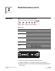
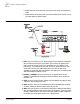

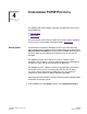
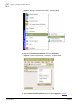
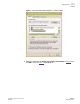
Table Of Contents
- iAN-02EX Release 1.0 Administrator Manual Issue 1.7
- Contents
- List of Tables
- List of Figures
- About This Guide
- Overview
- Hardware Installation
- Technical Specification
- Configuring TCP/IP Protocol
- Configuration
- Troubleshooting
- iAN-02EX Provisioning Methodology
- Provisioning overview
- Provisioning Features
- Provisioning Process rules
- Auto-Configuration
- Brief description on HTTP/TFTP Provisioning servers
- HTTP Provisioning servers
- Selection Prority for HTTP or TFTP servers
- Frequency of Upgrade
- Provisioning Server configuration files
- File format of the configuration File
- Encryption Engine
- Firmware Upgrade
- Provisioning Default Values
- UTStarcom, Provisioning Default Flag Values
- Sample Provisioning Flow Behavior
- Provisioning Flow
- Default Setting & Value
- iAN-02EX SNMP MIB Reference
- Upgrade Procedure
22
Chapter 2: Hardware Installation
iAN-02EX
Part Number UTSI-NJTC-200323150117
Administrator Manual
June 2005
■
ENET: Ethernet RJ-45 connector, connected to PC using a RJ-45 Ethernet
cable
■
WAN: Ethernet RJ-45 connector, connected to WAN access device, such as
the cable modem or ADSL modem
Installation Procedure
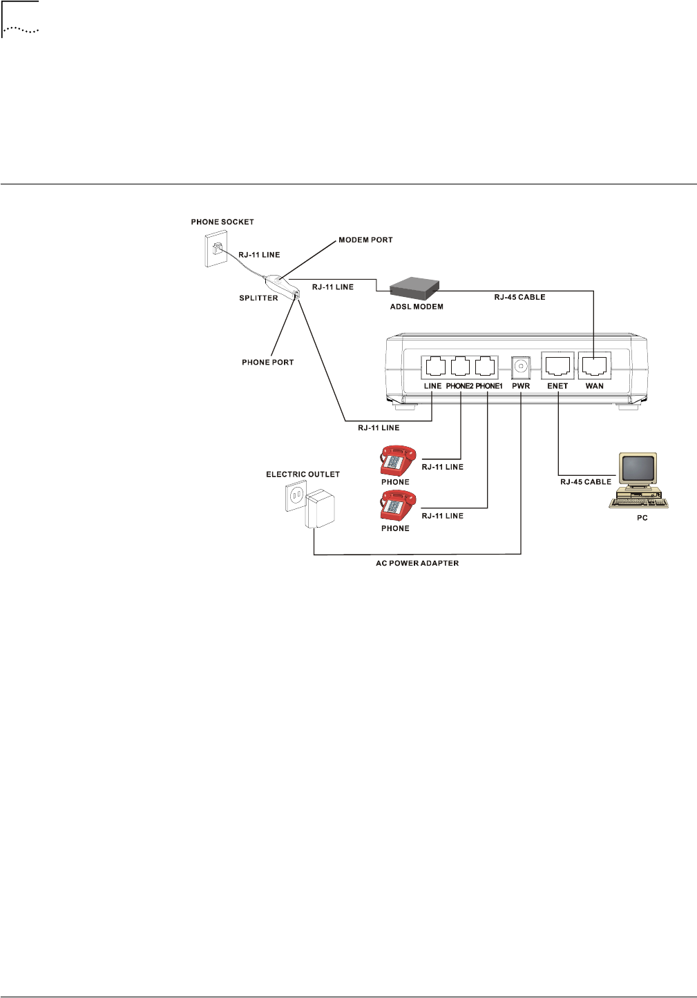
Figure 4
Installation Diagram
1LINE:
Plug one end of the RJ-11 telephone line into the LINE port and plug the
other end into the phone port of the splitter. Then connect the splitter to the
phone socket in the wall using a RJ-11 telephone line. The LINE port is for
back-up use. The telephone is using VoIP service by default. However, if the
2-port VoIP Gateway loses WAN connection or the VoIP function is not
available, the 2-port VoIP Gateway will make the telephone to use PSTN (Public
Switched Telephone Network) service.
2 PHONE1 & PHONE2:
Plug one end of the RJ-11 telephone line into the
PHONE1 or PHONE2 port and plug the other end into the phone socket on a
telephone set.
3PWR:
Plug one end of the power adapter into the PWR port and plug the other
end into an electric outlet in the wall.
4ENET:
Plug one end of the RJ-45 Ethernet cable into the ENET port and plug
the other end into the Ethernet socket of NIC on your PC.
5WAN:
Plug one end of the RJ-45 Ethernet cable into the WAN port and plug the
other end into the Ethernet port of the Internet service device, such as the cable
modem or ADSL modem. Then connect the cable modem or ADSL modem to
the modem port of the splitter using a RJ-11 telephone line.