
User's Manual


8 Chapter 2 Hardware Installation
User Guide WA3001-S Access Point
Note: 1. If you find anything missing or if the documentation set is
incomplete, contact your local dealer immediately.
2. The product is only for professional installation.
Interface Description
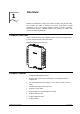
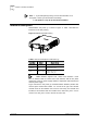
WA6011/6012 side panel (I) is shown in Figure 5. Table 1 describes the
interfaces on the side panel (I).
Figure 5 WA6011/6012 Side View (I)
220V
DATA
CONSOLE
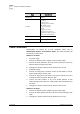
Table 1 Interface Description on Side Panel (I)
Interface Color Description
220V Red AC Power Connection Adapter
CONSOLE Green
RS232 port provides CLI
configuration interface
DATA
WA6011: Blue
WA6012: Yellow
Data Interface:
WA6011: Ethernet port;
WA6012: ADSL port
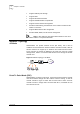
Note: WA6011 supports PoE
(
Power Over Ethernet
)
mode.
Use an Ethernet cable to connect AP’s Data interface with the DC power
output port in the DC power supply module to implement data transmission
and DC power supply.
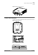
Figure 6 shows the side panel (II) of WA6011/6012. WA6011 provides four
antenna jacks marked with number 1 to 4 from left to right. Two wireless
network cards can be installed. Jack 2 & 3 are used if only one network card
installed; If two network cards are installed at the same time, jack 1 & 2 are
used for one card, jack 3 & 4 are used for the other card.