
User's Manual


12 Chapter 2 Installation Planning
12
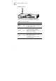
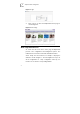
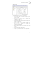
Figure 4 shows a schematic diagram of the backplane. Table 2
describes the interfaces and one button in the backplane.
Figure 4 Backplane
LAN1
LAN2
LAN3
LAN4
POWER
LI NE
PHONE
RESE T
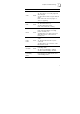
Table 2 Backplane Definition
Interfaces Type Description
POWER Barrel To connect to DC power
LAN1-LAN4 RJ45 To connect to PC
LINE RJ11 To connect to ADSL line
PHONE RJ11 To connect to phone
Reset Button
Recessed
pinhole
Hold down for 5 seconds, the
device will reboot and reset
to factory defaults
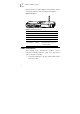
Cable Connections
After verifying proper environmental conditions such as
temperature, humidity and power supply, users may start the
cable connections as following:
1 Connect the PSTN line to the port marked “LINE” using a
RJ11 phone cable.