
User's Manual


10 Chapter 2 Installation Planning
10
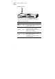
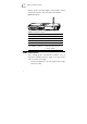
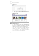
Figure 3 Faceplate
CAL L F W PWR
AL ARM
WLAN VOIP
LI NK
DAT A
LAN1LAN2
LAN3
LAN4
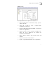
Table 1 describes LEDs and one button in the faceplate.
Table 1 Faceplate Definition
LED Name Color Definition
PWR
(Power)
Green
This LED indicates power status:
On: when power is applied to the device
Off: when power is off
ALARM Red
This LED indicates operational status:
On: when the hardware/software
malfunction is detected and not able to
continue normal operation
Off: when device operation is normal
WLAN Green
This LED indicates WLAN status:
Flash: when there’re wireless stations
accessed to the device
Off: when there’re no wireless stations
accessed to the device