Install Manual
Manuals
Brands
UTStarcom Korea Technologies Manuals
Electronics
Wireless Local Loop Phone System
36
37
38
39
40
41
42
43
44
45
Table Of Contents
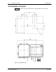
Equipment Description
200mW RP
List of Component Parts
Appearance of 200mW RP and Component Parts
200mW RP
Mounting Plate
M4 Screw
M6 Screw
M6 Spring Washer
M6 Plane Washer
M6 Nut
Joint Box
List of Component Parts
Joint Box Unpacking
Joint Box and Component Parts
Joint Box
Hexagon Socket Head Screw
M6 Spring Washer
M6 Plane Washer
M6 Nut
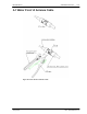
Wiring Cables to the Joint Box
Opening the Joint Box Cover
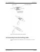
Making Connections
Names of the Connection Joints
Connecting the AC Power Cables and FG Cables
Connecting the Line Cables
Fixing the AC Power Cables and FG Cables
Fixing the Line Cables
Waterproof Treatment of the Line Cables
Closing the Joint Box Cover
Opening/Closing Cover of 200mW RP
Opening the Top Cover
Fixing the 200mW RP to the Mounting Plate
Closing the Top Cover
Appendix
A.1 200mW RP Cable Length
A.2 The Exchange of the Fuse
A.3 Electric Connection
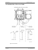
A.4 Example of Layout
A.5 Suitable Size of the Local Cable
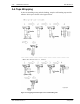
A.6 Tape Wrapping
A.7 Water Proof of Antenna Cable
A.8 Grounding Protective Earthing Cable
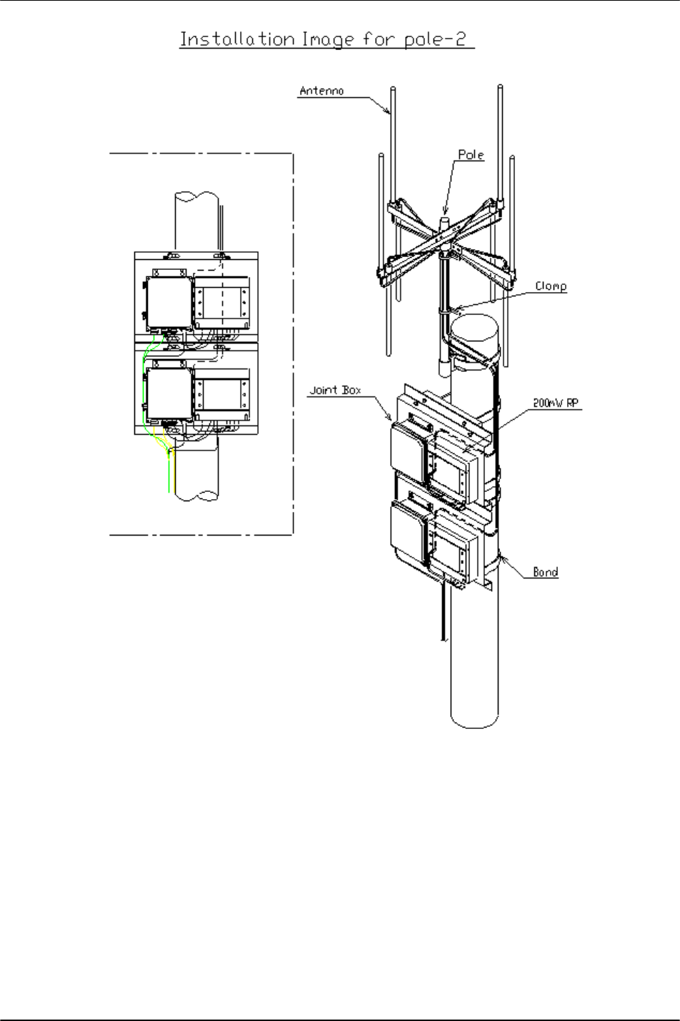
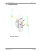
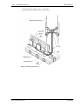
A.9 Installation Image
RPC/R
P Manual
200mW R
P Install
ation
25July
2000
WLL
-200m
W-R
P-IN-
1.0
3-43
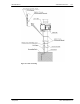
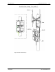
Figure 44: Pole I
nstallation
(2)
1
...
...
41
42
43
44
45