Install Manual
Manuals
Brands
UTStarcom Korea Technologies Manuals
Electronics
Wireless Local Loop Phone System
11
12
13
14
15
16
17
18
19
20
Table Of Contents
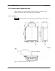
Equipment Description
200mW RP
List of Component Parts
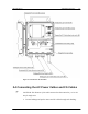
Appearance of 200mW RP and Component Parts
200mW RP
Mounting Plate
M4 Screw
M6 Screw
M6 Spring Washer
M6 Plane Washer
M6 Nut
Joint Box
List of Component Parts
Joint Box Unpacking
Joint Box and Component Parts
Joint Box
Hexagon Socket Head Screw
M6 Spring Washer
M6 Plane Washer
M6 Nut
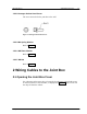
Wiring Cables to the Joint Box
Opening the Joint Box Cover
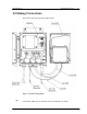
Making Connections
Names of the Connection Joints
Connecting the AC Power Cables and FG Cables
Connecting the Line Cables
Fixing the AC Power Cables and FG Cables
Fixing the Line Cables
Waterproof Treatment of the Line Cables
Closing the Joint Box Cover
Opening/Closing Cover of 200mW RP
Opening the Top Cover
Fixing the 200mW RP to the Mounting Plate
Closing the Top Cover
Appendix
A.1 200mW RP Cable Length
A.2 The Exchange of the Fuse
A.3 Electric Connection
A.4 Example of Layout
A.5 Suitable Size of the Local Cable
A.6 Tape Wrapping
A.7 Water Proof of Antenna Cable
A.8 Grounding Protective Earthing Cable
A.9 Installation Image
200mW R
P Instal
lation
RPC/R
P Manual
WLL-
200mW-RP-
IN-1.0
25July
2000
16
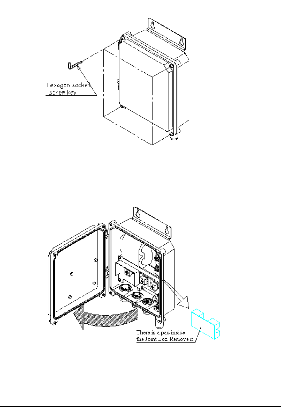
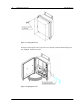
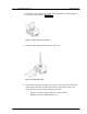
Figure 13: Loosing the Screws
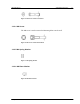
As shown in the figure below, open the cover slowly
to ensure that the hinges are
not damaged. Remove the pad.
Figure 14: Opening the Cover
1
...
...
14
15
16
17
18
...
...
45