
User Manual


RPC/RP Manual RPC Installation
19June2000 WLL-RPC/RP-IN/UM-1.0
2-
7
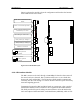
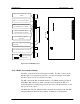
ALM : Red =fault detected on this
module
RUN : Green=normal operations
CHM : Green=E1 interface circuit
has established Layers 1 and 3
FSYC : Red=Frame out of
synchronization is dectected
LOS : Red=loss of signal is
dectected
AIS : Red=Alarm indication signal
is detected
RAI : Red=RAI signal is detected
RST Switch :
=Resets the entire
interface module
= Normal operations
Figure 2-6: E1IF Module Layout
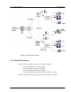
2.1.2.3 Radio Port Interface Module
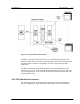
Each RPC controls and feeds a maximum of 32 RPs. The RPC connects to the
RPs through a 2-wire proprietary interface. Line power feeding from the RPC
provides a power source of 116V DC to the RPs.
The RPC controls the RPs via 8 RPIF modules. Each RPIF module provides an
ISDN Basic Rate interface to 4 RPs. The RP is extended from the RPC to a
maximum distance of 5.0km using a pair of φ0.5 wires and approximately 3.5 km
using a pair of φ0.4 wires.
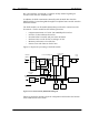
The Radio Port Interface (RPIF) module communicates externally with four RPs
through ISDN Basic Rate Interfaces (BRI). In addition, it communicates