
User Manual


RPC/RP Manual RPC Installation
19June2000 WLL-RPC/RP-IN/UM-1.0
2-
5
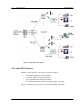
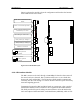
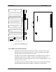
Figure 2-4 shows the module’s physical configuration and describes the function
of the LEDs and the reset switch.
System Reset Switch :
=Reset system
=Normal operations
ALM : Red =fault detected on this
module
RUN : Green=normal operations
SYNC : Green=E1 interface circuit
established Layers 1 and 3
LEDs 0 through 7 : Red=Frame
Rotary Switch (U) : Setting=0
Rotary Switch (L) : Setting=2
7
6
5
4
3
2
1
0
RMT or PC Connector
Alarm Reset Switch :
=Reset alarms
=Normal operations
Figure 2-4: ECNT Module Layout
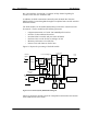
2.1.2.2 E1 Interface Module
The RPC connects to the COT through a 2.048 Mbps E1 Interface that carries all
the control and voice channels, that is, PCM encoded voice or voice band data,
between the COT and the RPC. The E1 Interface (E1IF) module communicates
externally with the COT through 1 G.703 E1 interface and uses Q.931 non-facility
associated signaling protocol.
Transmission between the RPC and RP is based on a proprietary, echo-canceled
transmission standard, which is similar to the recognized G.961 ISDN standard.
The E1IF provides the speech coding conversion between A-law PCM from the
COT and Adaptive Differential Pulse Code Modulation (ADPCM), which is ITU-