Wireless Local Loop RPC/RP Installation & Configuration Manual WLL-RPC/RP-IN/UM-1.
ii RPC/RP Manual Compiled by (Joseph) Guangping Zhang Copyright 2000 UTStarcom Inc. All Rights Reserved. This manual has been prepared for UTStarcom customers, UTStarcom personnel, and licensees. The information contained herein is the property of UTStarcom Inc. and shall be neither reproduced nor utilized in any form or by any means, electronically or mechanically, in whole or in part, without prior written approval from UTStarcom Inc. WLL-RPC/RP-IN/UM-1.
RPC/RP Manual iii Important Safety Instructions ! Safety Information: Installer and User WARNING The device is to be installed and operated at a “fixed location”. The term "fixed location" means that the device is physically secured at one location and is not able to be easily moved to another location. It must be located - (for indoor RPs) up on or near the ceiling away from users or bystanders – (for outdoor RPs) on the roof top site, pole, building, or traffic light away from users or bystanders.
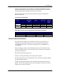
iv RPC/RP Manual Therefore, the transmitter model numbers EA7H74B and EA7H75B complies with the MPE requirements by providing a safe separation distance between the antenna (including any radiating structure) and any persons. The calculations were performed using formulas found in OET Bulletin 65 Edition 97-01(1997). Transmitter Specifications: Antenna Type Gain (dBi) Output power EIRP (dBm) Output Power (dBm) Base stations M/N 2.4 2.4 7 21.4 12.
RPC/RP Manual 19June2000 v • The telecommunication interfaces should not leave the building unless connected to telecommunication devices providing primary and secondary protection, as applicable. • This product should only be operated from the type of power source indicated on the marking label. • This equipment must be provided with a readily accessible disconnect device as part of the building installation. • Installation must include an independent frame ground drop to building ground.
vi RPC/RP Manual • This equipment is intended for installation in restricted access locations where access is controlled or where access can only be gained by service personnel with a key or tool. Access to this equipment is restricted to qualified service personnel. Save These Instructions! WLL-RPC/RP-IN/UM-1.
RPC/RP Manual vii Table of Contents 1 INTRODUCTION ...................................................................................................................................................1-1 1.1 P URPOSE ...................................................................................................................................................................1-1 1.2 ORGANIZATION ..............................................................................................................
viii RPC/RP Manual 4.2.4.1 RPC Status ...................................................................................................................................................4-22 4.2.4.2 RP Status .....................................................................................................................................................4-23 4.2.4.3 RP-I/F Board Status ........................................................................................................................
RPC/RP Manual 19June2000 ix WLL-RPC/RP-IN/UM-1.
x WLL-RPC/RP-IN/UM-1.
Introduction 1 1 Introduction 1.1 Purpose This manual describes the installation and configuration procedures for the Radio Port Controller (RPC) and Radio Port (RP). It is intended for the following customer personnel who participate in the engineering, installation, operations, and maintenance of the system. • • • • Equipment Engineers and outside plant engineers Installation, Operation, and Maintenance Personnel System Administrators Training Personnel 1.
1-2 Introduction RPC/RP Manual 1.3 Documentation Conventions Certain conventions are used in this document to denote types of information, such as commands, screen titles, options, and so on. The table below defines these conventions.
RPC/RP Manual 19June2000 Introduction 1-3 WLL-RPC/RP-IN/UM-1.
RPC Installation 2 2 RPC Installation 2.1 General Description The Radio Port Controller (RPC) functions as the controller and power distributor for the Radio Ports (RPs). It is also the concentrator of the speech paths and the protocol converter for the PHS protocol and the Q.931 protocol. It has Dual Tone Multi Frequency (DTMF) senders for dialing to the Local Exchange (LE) through the Central Office Terminal (COT).
2-2 RPC Installation RPC/RP Manual Figure 2-1: RPC in the WLL System 2.1.1 Main RPC Features An RPC consists mainly of four types of function modules: • • • • One ECNT (Enhanced Control) module Up to four E1IF (E1 Interface) modules Up to eight RPIF (RP Interface) modules One APL (Application Software Loading) module - Optional Figure 2-2 displays the four types of the function modules in the RPC. WLL-RPC/RP-IN/UM-1.
RPC/RP Manual RPC Installation 2-3 Figure 2-2: Function Modules inside the RPC Each RPC can handle traffic loads of up to 120 simultaneous telephone calls. Four E1 trunks connect to the COT side and support 30 subscriber channels each. In normal traffic conditions, a single RPC can service approximately 1000 subscribers. The RPC is monitored and controlled from the network management system connected to the COT.
2-4 RPC Installation RPC/RP Manual 2.1.2.1 Enhanced Control Module The ECNT module provides the Operation, Administration and Maintenance (OA&M) support for the RPC. In addition, it provides the time slot cross connect switch for communications between the E1IFs and the RPIFs. Figure 2-3 represents the ECNT functions.
RPC/RP Manual RPC Installation 2-5 Figure 2-4 shows the module’s physical configuration and describes the function of the LEDs and the reset switch.
2-6 RPC Installation RPC/RP Manual Rec.726 compliant, from the RP. It supports 32 kbps channel signaling for encoded voice and voice band data calls. In addition, the E1IF communicates internally with the Radio Port Interface (RPIF) module for interfacing RPs through the backplane busses and the switch in the ECNT module. The E1IF module is an E1 module (E1M) that provides 4 E1 connections to the E1 network. The E1 module has the following functions: • • • • • • Originates/terminates 4 G.703/G.704 2.
RPC/RP Manual RPC Installation 2-7 ALM : Red =fault detected on this module RUN : Green=normal operations CHM : Green=E1 interface circuit has established Layers 1 and 3 FSYC : Red=Frame out of synchronization is dectected LOS : Red=loss of signal is dectected AIS : Red=Alarm indication signal is detected RAI : Red=RAI signal is detected RST Switch : =Resets the entire interface module = Normal operations Figure 2-6: E1IF Module Layout 2.1.2.
2-8 RPC Installation RPC/RP Manual internally with the E1IF through the backplane busses and the switch in the ECNT module. Refer to Figure 2-7 for a block diagram of the RPIF module’s processing.
RPC/RP Manual RPC Installation 2-9 ALM : Red =fault detected on this module RUN : Green=normal operations SUS: Green=one or more Rps operational Not Lit=operations suspended on all connected RPs o Distance S w i Short L RP1 through RP4 : Green=normal operations Red=RP not connected, is faulty or is blocked t n c h g RST Switch : =Resets the entire interface module = Normal operations Figure 2-8: RPIF Module Layout 2.1.2.
2-10 RPC Installation RPC/RP Manual Figure 2-9: Application Module Layout 2.1.2.5 ADPCM Highway The ADPCM (Adaptive Differential Pulse Code Modulation) highway is the synchronous time multiplex digital voice/data path, and consists of up-stream and down-stream for Time Switch on the ECNT card. Time Switch and the digital voice and data paths on the E1IF cards and the RPIF cards are connected by the ADPCM highway. There are 8 ADPCM highways in an RPC.
RPC/RP Manual RPC Installation 2-11 Figure 2-10 shows the physical configuration of the rack mount type RPC. Figure 2-10: Layout of Rack Mount Type RPC The RPC is 532.6mm high, 482.6mm wide, and 265mm deep. 19June2000 WLL-RPC/RP-IN/UM-1.
2-12 RPC Installation RPC/RP Manual 2.3 Installation This section provides the instructions for installing an RPC. The flow chart in Figure 2-11 depicts the steps involved in the installation. Figure 2-11: RPC Installation Flow Chart 2.3.1 Before Beginning To ensure that the RPC installation goes smoothly, it is necessary to do adequate planning prior to the installation, including: • • • Location of the RPC Tools required Number of people needed to complete an installation. 2.3.
RPC/RP Manual RPC Installation • • • 2-13 Not in direct sunlight Free from extremes of heat, cold, and moisture 0° to 40° C ambient temperature 2.3.3 Tools Required Be sure to have the following necessary tools: • • • Screwdrivers Soldering iron and solder Tie bands for cabling 2.3.4 Installation Instructions Follow the steps below to install the RPC: 1. Carefully unpack the RPC and the accessories and make sure that they are in good condition.
2-14 RPC Installation RPC/RP Manual Figure 2-12: Unpacking the RPC and Accessories 2. Before installing the RPC in the rack, make sure to remove the card cover and the power source cover. F CAUTION: Do not take a photo with a flash once the card cover has been removed. RPC may not operate. 3. Loosen the thumbscrews. Tilt open the cover and slide it out as shown in Figure 2-13. WLL-RPC/RP-IN/UM-1.
RPC/RP Manual F RPC Installation 2-15 CAUTION: The card cover cannot hold itself when opened. Be sure to detach it from the cabinet. Figure 2-13: Removal of the Card Cover 4. Remove the 5 M3 screws in the power source cover and remove it, as illustrated in Figure 2-14. 19June2000 WLL-RPC/RP-IN/UM-1.
2-16 RPC Installation RPC/RP Manual Figure 2-14: Removal of the Power Source Cover F CAUTION: When inserting and removing each component, make sure to follow the proper electro-static discharge (ESD) procedures. 5. Connect and wire the power source and FG cables, as shown in the figure below. WLL-RPC/RP-IN/UM-1.
RPC/RP Manual RPC Installation 2-17 Figure 2-15: Power and FG Cable Connectors 6. Insert the RPC in the rack and fasten to the rack with 8 screws as indicated in Figure 2-16. F 19June2000 CAUTION: Make sure the RPC is firmly mounted in the rack. Serious injury could occur if the RPC fell out of the rack. WLL-RPC/RP-IN/UM-1.
2-18 RPC Installation RPC/RP Manual Figure 2-16: Mounting the RPC in the Rack 7. After installing the RPC in the rack, affix the wiring as indication in Figure 2-17. Redirect the support according to the direction of the wiring, as shown in Figure 2-17. WLL-RPC/RP-IN/UM-1.
RPC/RP Manual RPC Installation 2-19 Figure 2-17: Wiring – Back of RPC 8. Connect the coaxial cable with an SMB coaxial cable plug having an impedance of 75 ohms into the E1IF connectors on the back of the RPC, as shown in Figure 2-17 9. Connect the cable with a Champ plug to the RPIF connector on the back of the RPC. Refer to Figure 2-17. Table 2-1 provides the maximum cable lengths between the RPC and the RP for 2 different wire gauges.
2-20 RPC Installation Wire Guage φ0.4 m φ0.5 m RPC/RP Manual Maximum Cable Length 3.5Km 5.0Km Table 2-1: Maximum RP Cable Length F NOTE: Be sure to use a twisted pair cable or a 2 pair twisted cable. Avoid any 2 pair twisted cable splits before connecting cables. 10. When the RP and E1 cables are connected, attach the cabling to the supports with tie bands. Refer to Figure 2-18. F NOTE: Tie Bands are to be prepared on-site. Figure 2-18: Cabling Example WLL-RPC/RP-IN/UM-1.
RPC/RP Manual RPC Installation 2-21 11. Install the modules in the RPC slots according to the labels on the cabinet. Refer to Figure 2-19 for the slot assignment. F NOTE: The APL module is installed only when the software upgrades are unsuccessful without it. It is not intended to remain in the system during normal operations. Figure 2-19: RPC Slot Assignment 12. Make sure that the rotary switches on the ECNT module are correctly set before applying power.
2-22 RPC Installation Switch Name Rotary Switch (U):S4 Rotary Switch (L):S5 RPC/RP Manual Setting 0 2 Table 2-2: Rotary Switch Settings 13. Slide the card into the RPC shelf using the upper and lower slot guides. When properly seated, the lower edge of the card is recessed from the outer edge of the lower slot guide. And the upper edge of the card is flush with the outer edge of the upper card guide. Refer to Figure 2-20. WLL-RPC/RP-IN/UM-1.