
User Manual

Specifications RPC/RP Manual
WLL-RPC/RP-IN/UM-1.0 19June2000
A-2
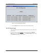
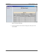
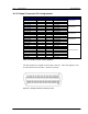
A.1.1 Champ Connector Pin Assignments
Assignment Pin # Pin # Assignment Remarks
RP # 1 (L1) 1 26 RP # 1 (L2)
RP # 2 (L1) 2 27 RP # 2 (L2)
RP # 3 (L1) 3 28 RP # 3 (L2)
RP # 4 (L1) 4 29 RP # 4 (L2)
RPIF Card #1
RP # 5 (L1) 5 30 RP # 5 (L2)
RP # 6 (L1) 6 31 RP # 6 (L2)
RP # 7 (L1) 7 32 RP # 7 (L2)
RP # 8 (L1) 8 33 RP # 8 (L2)
RPIF Card #2
RP # 9 (L1) 9 34 RP # 9 (L2)
RP# 10 (L1) 10 35 RP # 10 (L2)
RP# 11 (L1) 11 36 RP # 11 (L2)
RP# 12 (L1) 12 37 RP # 12 (L2)
RPIF Card #3
RP# 13 (L1) 13 38 RP # 13 (L2)
RP# 14 (L1) 14 39 RP # 14 (L2)
RP# 15 (L1) 15 40 RP # 15 (L2)
RP# 16 (L1) 16 41 RP # 16 (L2)
RPIF Card #4
Not in use 17 42 Not in use
Not in use 18 43 Not in use
Not in use 19 44 Not in use
Not in use 20 45 Not in use
Not in use 21 46 Not in use
Not in use 22 47 Not in use
Not in use 23 48 Not in use
Not in use 24 49 Not in use
Not in use 25 50 Not in use
No need to attach
Table A-2: Champ Connector 1-Pin Assignments
The Pin numbers are marked on the Champ connector. This chart applies to J16
on the motherboard in the RPC. RP has no polarity.
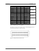
Figure A-1: Champ Connector Contact Face View