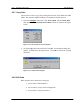
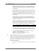
4-46 RPC/RP Configuration RPC/RP Manual 4.3.7 Copy Data This function is used to copy the operating data from the ACT SDM to the SBY SDM. The automatic SDM switching is not supported for this function. 1. From the Configure main menu, click Service Data, and then Write Data. This opens the Write System Service Data window, as shown in the figure below. Figure 4-52: Write System Service Data Window 2. Click the Copy radio button and then click OK.
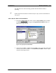
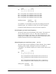
RPC/RP Manual RPC/RP Configuration 4-47 Use this function to edit an existing operation data file while the RPC is operating. F NOTE: Operation data must be edited locally in a file, and then downloaded to the system. 4.3.8.1 Service Data 1: RP Installation 1. From the Configuration main menu, click the Service Data option, and then the Edit Data option. This brings up the Specify File for Edit window, as shown in the figure below. Figure 4-54: Specify file for Edit Window 2. Select the target .
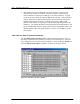
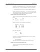
4-48 RPC/RP Configuration RPC/RP Manual Figure 4-55: Edit of Service Data 1 Window Field Name RP# Inst. Phantom Local Save Next Cancel Switch 1,2,3 Description RP ID number Set “installed” or “not installed” for RPs according to RP installation plan. The power is supplied by the RPC. The power is supplied by the RP power unit. Save the setting to a local file. Switch to the next Service Data window. Cancel the editing. Switch to one of the three Service Data windows.
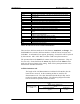
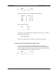
RPC/RP Manual RPC/RP Configuration 4-49 Figure 4-56: Edit of Service Data 2 Window Field Name RP-I/F Group # RP# Master Save Next Description RP interface ID number Group ID number RP ID number Master/Slave status of the RPs Save the Service Data toa a file.
4-50 RPC/RP Configuration RPC/RP Manual 2. This window is for the configuration of Group Control. Group Control maximizes the number of channels available for traffic by allowing one control channel to control up to 8 RPs (up to 31 traffic channels). A group can be set up only within two adjacent RP interface boards. Group members must be within the two RP Interface boards. For each RP, enter the group number and designate the master.
RPC/RP Manual RPC/RP Configuration Field Name No. Value Item Basic Unit Min Max HEX val. Button Name Target Item Basic Range < > << >> Save Top 4-51 Definition Item sequence numbers, starting from 1 Specified value for the item. The value can be selected from the arrow drop-down list.
4-52 RPC/RP Configuration RPC/RP Manual Operator ID Code: MSB is always set to "1". The remaining 8 bits are used for Operator ID. The Operator ID’s of all RPs that connect to the same RPC take the same value, and the value is equal to the setting value of this data field. Paging Area Number refers to the area where the call is broadcast for the FSU or PS that has location registration for that area.
RPC/RP Manual RPC/RP Configuration Bit Bit 1 Bit 2 Bit 3 Bit 4 MSB 8 7 6 0 0 0 5 0 4-53 LSB 4 3 2 1 X X X X corresponds to the installation status of E1-IF#1 corresponds to the installation status of E1-IF#2 corresponds to the installation status of E1-IF#3 corresponds to the installation status of E1-IF#4 Installation status: Installed à1 Not installed à 0 Set "installed" or "not installed" for each E1-IF according to the E1-IF installation plan.
4-54 RPC/RP Configuration RPC/RP Manual For instance, if Channel frequency No. 1, 3, 5 are available and Channel frequency No. 2, 4, 6, 7, 8 are unavailable, the values are set as follows: Channel frequency use control (1-8): 0001 0101(Binary) (HEX: 15) Channel frequency use control (9-16) ….. (73-77) are set in the same way. The previous and the next Channel frequency of LCCH frequency must be set "Unavailable" for traffic channel to avoid the interference.
RPC/RP Manual RPC/RP Configuration Bit MSB 8 7 6 0 0 0 5 y 4 x 3 x 4-55 LSB 2 1 x x Bit 1-4 (xxxx) are the value of loudness, as listed below: Real level 0 dB 2 dB 4 dB 6 dB ............... à à à à Bit 4 0 0 0 0 3 0 0 0 0 2 0 0 1 1 1 0 1 0 1 Bit 5 is the value of sign. Sign Bit 5 à 1 à 0 ...................
4-56 RPC/RP Configuration RPC/RP Manual Bit 1-4 (xxxx) are the value of loudness, as listed below: Real level 0 dB 2 dB 4 dB 6 dB ............... à à à à Bit 4 0 0 0 0 3 0 0 0 0 2 0 0 1 1 1 0 1 0 1 Bit 5 is the value of sign. Sign Bit 5 à 1 à 0 ................... For instance, if the output loudness of RPC needs to be set to + 8 dB, the setting value is as follows: 0001 0100 (Binary) This value is determined in accordance with the system level plan.
RPC/RP Manual RPC/RP Configuration 4-57 Country number 1, 2 This item is used for the setting of Country Code. The Country code is used to represent the country which assigns the RP identification code. System type This item is used for the setting of system type. This system is applicable for the system. The system type is 3. The coding is "0000 0100" (Binary). Standby zone selection level This item is used for the setting of air-interface.
4-58 RPC/RP Configuration RPC/RP Manual FSU mobility limitation This item is used for the control of FSU mobility limitation. Depending on the setting value, one mode might be that RPC reports RP-ID to WLL/V5WLL for mobility, the other mode might be that RPC doesn't report RP-ID to WLL/V5WLL for mobility. In the case that RPC reports RP-ID to WLL/V5WLL, WLL/V5WLL controls FSU mobility in accordance with the subscriber setting.
RPC/RP Manual RPC/RP Configuration 4-59 Figure 4-58: RP Installation (Group Composition 1) Window 2. This window is used to configure RP connection. For each installed RP, enter a √ in the Inst. row. For each installed RP, specify the power source by clicking on either the Phantom button or the Local button. Phantom means the power is supplied by the RPC. For WLL, the power source is Phantom. 3. To get to the RP Installation (Group Composition 2) window, click Next or Switch 2.
4-60 RPC/RP Configuration RPC/RP Manual 4. This window is for the configuration of Group Control. Group Control maximizes the number of channels available for traffic by allowing one control channel to control up to 8 RPs (up to 31 traffic channels). Each group contains two RP Interface boards. Group members must be within the two RP Interface boards. For each RP, enter the group number and designate the master.
RPC/RP Manual RPC/RP Configuration 4-61 Figure 4-61: E1-IF Board Installation 3. Check or uncheck the boxes in front of the target E1 interfaces to be installed or uninstalled, and click OK. 4.3.11 Change Data (Data Value) Use this function to change the operation data value. F NOTE: This feature is not recommended. Use with care. 1. From the Configuration main menu, click Service Data, then Change Data, and then Data Value. The Data Value Change window opens, as illustrated in the figure below.
4-62 RPC/RP Configuration Field Name No. Value Item Basic Unit Min Max HEX addr. Button Name Item Basic Range < > << >> OK RPC/RP Manual Definition Item sequence numbers, starting from 1 Specified value for the item. The valid values are displayed in the Item block and can be selected from the arrow drop-down list.
RPC/RP Manual RPC/RP Configuration 4-63 2. To view the RPC warnings, click the Status main menu, and select the Warning option. The Warning window appears, as displayed in the figure below. Another way to open the window is to click the Warning button. Figure 4-63: Warning Window 3. Click the Update button to retrieve the latest information. The color of the small rectangle in front of each warning message indicates the alarm’s severity.
4-64 RPC/RP Configuration RPC/RP Manual 1. To view the log of the Alarm History, select the Alarm History option from the Status main menu. The Alarm History window appears as shown in the figure below. Another way to open the window is to click the Fault History button. Figure 4-64: Alarm History Window F NOTE: This log has a capacity of storing 127 messages. When this limit is reached, the oldest message is deleted when the newest one is added. 2. Click Update to display the historical information.
RPC/RP Manual RPC/RP Configuration 4-65 button or click Air Channel on the Unit View window of the RPC window to open the Channel Status View window. After resetting, unblock the unit. 1. On the Main View window, click the target RPC-DM node and connect to the RPC. This opens the RPC window. 2. Select the Reset option from the Maintenance pull-down menu or click the Reset button. The Reset window appears, as shown in the figure below. Figure 4-65: Reset RPC Window 3.
4-66 RPC/RP Configuration RPC/RP Manual Figure 4-67: EM Reset (RPC) Window Field Name Startup System Prev. N System E System Description Determine which SDM to use for operating RPC after resetting. Previous ACT SDM. After resetting, RPC starts up and runs based on the previous ACT SDM. SDM-#N. After resetting, RPC starts up and runs based on SDM-#N. SDM-#E. After resetting, RPC starts up and runs based on SDM-#E. Table 4-16: EM Reset (RPC) Window Field Description F NOTE: Refer to Section 4.
RPC/RP Manual RPC/RP Configuration 4-67 4.6 RPC Statistics The function of RPC statistics can generate an RPC traffic report that displays the traffic status for either the entire period and all the RPCs and RPs, or the specific period and an individual RPC or RP. This is a useful feature for analyzing the RPC traffic. In addition, the RPC statistics can also create the RP status report. 4.6.1 RPC Traffic Report 1.
4-68 RPC/RP Configuration RPC/RP Manual Figure 4-70: RPC/RP Traffic Report Window F NOTE: Sometimes nothing happens after the Refresh button is clicked. The reason is that the RPC board may have been reset by RTs and there is no synchronization between the RPC device manager and the RPC board. In that case go to the RPC System View window, click open the Configure main menu, and select Set Time. The Set Time window opens. Click OK to synchronize the RPC device manager with the RPC board.
RPC/RP Manual RPC/RP Configuration 4-69 Figure 4-71: Description of RPC Traffic Status 4.6.2 RPC Outstanding Alarms RPC Outstanding Alarms list all the alarms for each RPC which haven’t been fixed. 1. To display the RPC outstanding alarms, click the Statistics main menu on the Client View window and select the RPC Outstanding Alarms option. This brings up the RPC Outstanding Alarm window, as shown in Figure 4-72. 19June2000 WLL-RPC/RP-IN/UM-1.
4-70 RPC/RP Configuration RPC/RP Manual Figure 4-72: RPC Outstanding Alarm Window 2. Click the Refresh button to retrieve the current outstanding alarms. 4.6.3 RP Status Report This feature displays the blockade and warning statuses for all the 32 RPs of the selected RPC. 1. To view the report, click the Statistics main menu and select the RP Status Report option on the Client View window. The RP Status Report page opens on the Main View window, as shown below. WLL-RPC/RP-IN/UM-1.
RPC/RP Manual RPC/RP Configuration 4-71 Figure 4-73: RP Status Report Page 2. Select the target RPC on the left frame to bring up the status report for the associated RPs. 19June2000 WLL-RPC/RP-IN/UM-1.
4-72 RPC/RP Configuration WLL-RPC/RP-IN/UM-1.
Specifications A A Specifications A.1 RPC Specifications Item Functions Capacity Max. number of controlled subscribers Max. number of controlled RPs Max. number of COT interfaces Max. speech paths COT Interface Physical Interface Speech coding rule Logical Interface RP Interface Physical Interface Speech coding rule Line power feeding voltage Logical Interface Power Condition Input voltage Max.
A-2 Specifications RPC/RP Manual A.1.
RPC/RP Manual Specifications Assignment RP # 17 (L1) RP # 18 (L1) RP # 19(L1) RP # 20(L1) RP # 21(L1) RP # 22(L1) RP # 23(L1) RP # 24(L1) RP # 25(L1) RP# 26 (L1) RP# 27(L1) RP# 28(L1) RP# 29(L1) RP# 30(L1) RP# 31(L1) RP# 32(L1) Not in use Not in use Not in use Not in use Not in use Not in use Not in use Not in use Not in use Pin # 1 2 3 4 5 6 7 8 9 10 11 12 13 14 15 16 17 18 19 20 21 22 23 24 25 Pin # 26 27 28 29 30 31 32 33 34 35 36 37 38 39 40 41 42 43 44 45 46 47 48 49 50 Assignment RP # 17 (L2) RP #
A-4 Specifications RPC/RP Manual A.2 RP Specifications A.2.1 Radio Features Item Radio frequency Carrier spacing Output power Radio access Number of TDMA slots Modulation Transmission bit rate Speech coding Contents For private use: 1,895-1,906.1 MHz For public use: 1,895-1,910 MHz 300 KHz 10 mW TDMA-TDD 4 (for full rate CODEC) π/4 shift QPSK (roll-off factor = 0.5) 384 kbps 32 kbps ADPCM Table A-4: Radio Features A.2.
RPC/RP Manual Specifications A-5 A.2.2.1 Antenna The recommended antenna specifications for the outdoor type RP are shown in Table A-6. Items: Type Gain Impedance VSWR Cable Recommended Specifications Co-Liner antenna (Omni-directional) 2 branch 7dBi 50Ω less than 1.5 Length: within 1m Attenuation: 0.5dB/m Table A-6: Antenna Specifications - Outdoor Type RP A.2.
A-6 Specifications WLL-RPC/RP-IN/UM-1.
Glossary B B Glossary 19June2000 ADPCM Adaptive Differential Pulse Code Modulation BRI Basic Rate Interface CNT Control Module COT Central Office Terminal CPU Central Processing Unit CRC Cyclic Redundancy Check E1IF E1 Interface ECNT Enhanced Control Module FIFO First In - First Out HDLC High speed Digital Loop Carrier HDSL High speed Digital Subscriber Loop ISDN Integrated Services Digital Network ITU International Telecommunications Union LE Local Exchange LED Light Emitti
B-2 Glossary RPC/RP Manual PCM Pulse Code Modulation PHS Personal Handyphone System RAM Random Access Memory ROM Read Only Memory RP Radio Port RPC Radio Port Controller RPIF Radio Port Interface TIF Trunk Interface WLL-RPC/RP-IN/UM-1.
RPC/RP Manual 19June2000 Glossary B-3 WLL-RPC/RP-IN/UM-1.
Editor’s Note C C Editor’s Note C.1 Notice to Customers UTStarcom reserves the right to change the specifications and materials contained herein without notice, and shall not be responsible for any damages caused by reliance on the material as presented, including, but not limited to, typographical, arithmetic, and listing errors. Trademarks All trademarks and service marks used in this document belong to their respective owners.
C-2 Editor’s Note RPC/RP Manual UTStarcom (China) Ltd. th Zhejiang Unitel Telecommunications Equipment Ltd CNT Manhattan Building, 11 Floor 6 Chao Yang Men Bei Da Jie Dong Cheng District, Beijing, 100027 P.R. China Tel. 86-10-6554-2030 Fax 86-10- 6554-2058 3 Yile Industrial Park 3/4F Building 129 Wen Yi Rd. Hangzhou, 310012, P.R. China Tel. 86-571-886-2341 Fax 86-571-886-2349 UTStarcom, Shanghai Office Guangdong UTStarcom Co. Ltd. Rm 1901-1902 227 Huang Pi North Road Shanghai, 200237, P.R.
RPC/RP Manual Editor’s Note C-3 C.2 How to Comment on This Document UTStarcom strives to continuously improve its products and services to better help our customers succeed. As our valued customer, you can help us by giving us your comments on this manual. A feedback form is located on the next page. Please take a few minutes to complete the form and send it to the following address by mail or fax. If you have any comments and suggestions, please send them to this address, too.
C-4 Editor’s Note WLL-RPC/RP-IN/UM-1.
RPC/RP Manual Editor’s Note C-5 C.
C-6 Editor’s Note RPC/RP Manual Please tell us about yourself: Company Title / Job Responsibility Years of Experience In case we contact you, please provide the following (optional): Your Name Phone Number E-mail Address ------------------- fold along line ----------------------------------------------------------------------------------------------------tape here ------------------- fold along line ----------------------------------------------------------------------------------------------------PostO
RPC/RP Manual 19June2000 Editor’s Note C-7 WLL-RPC/RP-IN/UM-1.