
User Manual

RPC Installation RPC/RP Manual
WLL-RPC/RP-IN/UM-1.0 19June2000
2-
26
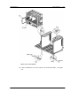
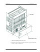
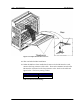
Figure 2-23: Replacement of the Card Cover
18. This concludes the RPC installation.
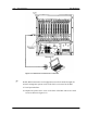
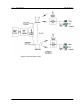
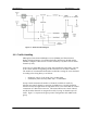
19. When the RPs have been installed and connected to the RP Interface cards,
measure the loop resistance of the cable. Then set the Distance Switch on the
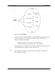
RP Interface card based on the loop resistance value. Refer to the table and
figure below. The factory setting is Short.
Setting Loop Resistance
Long 150Ω or more
Short Less than 150Ω
Table 2-3: Distance Switch Settings