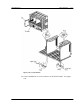
RPC/RP Manual RPC Installation 2-23 Figure 2-20: Card Installation 14. Connect the RMT or PC to the connector on the ECNT module. See Figure 2-21. 19June2000 WLL-RPC/RP-IN/UM-1.
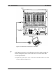
-24 RPC Installation RPC/RP Manual Figure 2-21: Maintenance Terminal or PC Connection F NOTE: RPC maintenance and configuration can also be made throught the network management system via the COT which is connected to the RPC. 15. Load operation data. 16. Replace the power source cover on the front of the RPC and secure it with screws as shown in Figure 2-22. WLL-RPC/RP-IN/UM-1.
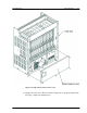
RPC/RP Manual RPC Installation 2-25 Figure 2-22: Replacement of Power Source Cover 17. Replace the card cover. Make certain the hinge pins are properly aligned with the hinge. Tighten the thumbscrews. 19June2000 WLL-RPC/RP-IN/UM-1.
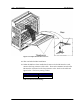
2-26 RPC Installation RPC/RP Manual Figure 2-23: Replacement of the Card Cover 18. This concludes the RPC installation. 19. When the RPs have been installed and connected to the RP Interface cards, measure the loop resistance of the cable. Then set the Distance Switch on the RP Interface card based on the loop resistance value. Refer to the table and figure below. The factory setting is Short.
RPC/RP Manual RPC Installation 2-27 Figure 2-24: Distance Switch 19June2000 WLL-RPC/RP-IN/UM-1.
2-28 RPC Installation WLL-RPC/RP-IN/UM-1.
RP Installation 3 3 RP Installation 3.1 General Description The Radio Port (RP) is the radio equipment base station that relays the communication from the user side to the operator/network side or vice versa. A standard installation for RP applications places several RPs in a common service area.
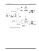
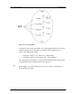
3-2 RP Installation RPC/RP Manual Figure 3-1: RP in the WLL System WLL-RPC/RP-IN/UM-1.
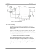
RPC/RP Manual RP Installation 3-3 Figure 3-2: Radio Port Block Diagram 3.1.1 Traffic Handling PHS applies Time Division Multiplex Access (TDMA) and Time Division Duplex (TDD) techniques. Each individual radio link between the RP and the FSU/PS is assigned 1 time slot for a control channel (C-ch) and 3 slots for traffic channels (T-chs). In the case of a single RP, there are 4 time slots installed for radio links. One slot is the control channel for signaling and the other three are the traffic channels.
3-4 RP Installation RPC/RP Manual Figure 3-3: Group Control RPs In the group control mode, the number of accommodated subscribers in the group control coverage zone is calculated in accordance with the erlang theory as follows (with 4 RPs in the group): • • Erlang per zone (15 T-chs, GOS=5%) = 10.663 erlang Subscribers (FSUs or PSs) (10.663÷.08) = 132 subscribers The comparison for the number of accommodated subscribers between the group controlled RPs and the single RP is shown in Figure 3-4.
RPC/RP Manual RP Installation 3-5 Figure 3-4: Accommodated Subscribers per RP in Group and Non-group Control The recommended installation design for RPs is as follows: • • A zone of sparse subscribers should be covered by non-group controlled RPs. A zone of dense subscribes should be covered by group-controlled RPs. The number of accommodated subscribers is the greatest when all of the RPs connected to an RPC are configured in the group control mode.
3-6 RP Installation RPC/RP Manual Figure 3-5: Coverage Service Area with Cell Overlap The combination of Cell Overlap and Dynamic Channel Allocation increases the flexibility and the capacity of the system. Every user has access to all channels (77x4) due to the overlapping base station topology. Cell Overlap enhances the reliability and service quality. One malfunctioning base station does not affect the performance of the system.
RPC/RP Manual RP Installation 3-7 Figure 3-6: Radio Channel Structure The radio frequency allocation shown in Figure 3-6 displays a typical radio channel structure when three cordless handsets are operating through a single RP. RCR STD-28 does not designate a control channel prior to the operation. Instead, it assigns the control slot to any one of the four available slots. Traffic channels are not preassigned.
3-8 RP Installation RPC/RP Manual quality. TDMA enables the antennas to share both transmitting and receiving with the RF switches. To implement receiving diversity, the receiving units have two receiving branches, while the transmitting unit has switches for switching antennas to provide the transmission diversity. 3.2 System Construction Figure 3-7 represents the RPC and RP configuration. WLL-RPC/RP-IN/UM-1.
RPC/RP Manual RP Installation 3-9 Figure 3-7: RPC and RP Configuration The dimensions of the indoor Radio Port are as follows: • 19June2000 Height:142 mm WLL-RPC/RP-IN/UM-1.
3-10 RP Installation • • RPC/RP Manual Width:154 mm Depth:47 mm The dimensions of the outdoor Radio Port are as follows: • • Height:214±2.5 mm Width:260±2.5 mm 3.3 Indoor RP Installation Instructions This section provides the instructions for installing an indoor RP. The flow chart in Figure 3-8 describes the steps involved in the installation. Figure 3-8: Indoor RP Installation Flow Chart 3.3.
RPC/RP Manual RP Installation 3-11 3.3.2 Site Selection For indoor RP installation, select a site that satisfies the following requireme nts: • • • • F Less than 3 meters from the RP antenna Not in direct sunlight or near a heat source such as a radiator Free from excessive humidity; not more that 95% non-condensing Free from excesses of heat or cold, not lower than -10°C nor higher than +50°C NOTE: If more than 3 meters , consult a qualified field engineer. 3.3.
3-12 RP Installation RPC/RP Manual 3. Insert the RJ-11 end of the RPC cable into the connector on the back of the indoor RP. Refer to Figure 3-10. Figure 3-10: Connection to RPC 4. Attach the indoor RP to the mounting plate with the special screw as indicated in Figure 3-11. WLL-RPC/RP-IN/UM-1.
RPC/RP Manual RP Installation 3-13 Figure 3-11: Indoor RP and Mounting Plate 5. This concludes the installation of the indoor RP. 3.4 Outdoor RP Installation Instructions This section provides the instructions for installing the outdoor RP. The flow chart in Figure 3-12 defines that steps involved in the installation. 19June2000 WLL-RPC/RP-IN/UM-1.