
User Manual

RPC/RP Manual RPC/RP Configuration
19June2000 WLL-RPC/RP-IN/UM-1.0
4-
19
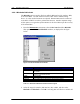
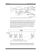
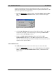
Figure 4-21: Clock Synchronization and Frame Synchronization in One RPC
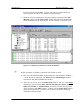
However, RPs that belong to different RPCs do not automatically operate with air
frame synchronization. This causes the inefficienct air channel usage. To redress
the problem, the synchronization group is created which includes as many as 8
RPCs. Those RPCs are connected by cables as open daisy chain, through which
the air frame synchronization signal is transmitted. The signal is shared by the
RPCs, so that the air frames of the RPs among the RPCs are synchronized. The
RPC which generates the air frame synchronization signal is named “Master”.
The RPCs which receive the signal are called “Slave”. The following figure
displays such a synchronization model.
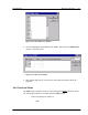
Figure 4-22: Wired Air Frame Synchronization Group Model
The master or slave mode is set using the rotary switches on the front of the
ECNT board. When the master RPC fails during the operation, the first slave
RPC in the synchronization signal flow becomes the provisional master RPC.