
User Manual

RPC/RP Configuration RPC/RP Manual
WLL-RPC/RP-IN/UM-1.0 19June2000
4-
30
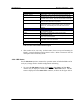
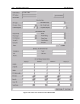
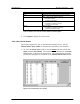
Field Name Definition
E1#1 Corresponding to E1-I/F#1, Bch#1 - 30
E1#2 Corresponding to E1-I/F#2, Bch#31 - 60
E1#3 Corresponding to E1-I/F#3, Bch#61 - 90
E1#4 Corresponding to E1-I/F#4, Bch#91 - 120
Layer 1 Physical layer with SAPI=0,16
Layer 2 (SAPI=0) Data Link layer for call processing
Layer 2 (SAPI=16) Data Link layer for HOST interface
Layer 3 (SAPI=16) Network layer for HOST interface
Master Master E1 on which D-channel is established.
Slave Slave E1
Warning There is a warning for the E1.
No warn There is no warning for the E1.
Table 4-6: Signal Status Field Name Definition
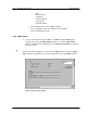
2. Click Update to display the current status.
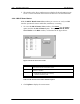
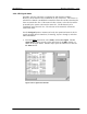
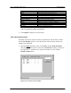
4.2.4.5 E1 Interface Status
Each RPC has four E1 interface boards to communicate with the WLL/V5WLL.
Use the E1 Interface option to verify E1 Interface status, monitor alarms, and
identify areas of trouble.
1. From the Status pull-down menu, click Status, and then Node-I/F Board.
This displays the E1 Interface status on the Status View window, as shown in
the figure below. Another way to open this window is to click the E1-
Interface Status button.
Figure 4-31: E1 Interface Status Window