
User's Manual


40mW ACS User Guide Technical Introduction v
PAS System
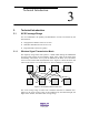
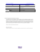
TDMA-TDD Frame (5ms)
CS Transmission PHS PS Transmission
CS
PHS
PS #2
PHS
PS #3
PHS
PS #1
CCH
T2
T4
CCH
R4
R2
T2
R2
CCH
R4
T4
CCH: signaling channel
T2,T4: communication channel (to transmit)
R2,R4: communication chanenl (to receive)
PAS Handset #1: signaling channel, waiting
PAS Handset #2: 2
nd
time slot, calling
PAS Handset #3: 4
th
time slot, calling
T2
R2
: transmission time slot
: receivin
g
time slot
: idle time slot
R2
R4
R4
R4
R2
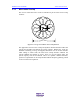
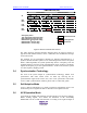
Figure3-5 Wireless Channel Frame Structure
The radio frequency channel allocation diagram shown in Figure3-5 depicts a
typical wireless channel structure, where, 3 subscribers can communicate in single
ACS control mode.
The channels are not preassigned; channels are allocated automatically by a
dynamic channel allocation system. It is an outstanding feature of the PAS system.
With a settled algorithm, the system dynamically chooses a frequency from the
available frequency resources as the communication carrier frequency, and timely
adjusts the frequency as per the signal disturbance. In this sense, the PAS system
is a slow frequency-hopping system.
3.4 Synchronization Technology
The ACS in the system adopts air synchronization technology. Master ACS
synchronizes with other master ACSs via GPS. By receiving the air
synchronization signal from master ACS, slave ACS synchronize with master
ACS. For RPC synchronization solution, please refer to “GSG2 user guide”.
3.5 Self-Adaptive Mode
ACS is a kind of self-adaptive CS, which can adjust its transmission power. The
transmission power ranged from 0mW to 200 mW can be adjusted on-line.
3.6 ACS Operation Mode
ACS adopts the sending after detecting operation mode (receiving then sending).
Before sending signals, ACS detects the utilization of the surrounding
WIRELESS LOCAL LOOP radio channels. According to the signal strength of