User’s Manual January, 2003
Definition & Acronyms ACS ADPCM ATC BRI CCM CDR CO CS RPC CSIF DDF DTMF DWRT E1-IF E1MW EBAM ECNT FDDI FSK FSU FXOW GND HGND HLR IP LE LED MCU MDF NMS OAM&P PAS PC PDP PGT PGTC PGTS PHS Adaptive Cell Station Adaptive Differential Pulse Code Modulation Air Traffic Controller Basic Rate Interface CS Control Module Call Description Record Central Office Cell Station CS Controller CS Interface Module Digital distributed Frame Dual Tone Multi Frequency Data Wireless Remote Terminal E1 Interface Module W1 Module
PIAFS PS PSM PSTN QFE RCM RF RP RPC RP-IF RT RX RxD SATC SCMW TCM TE1M TX TxD VLR PS-PHS Internet Access Forum Specification Personal Station Power Supply Module Public Switched Telephone Network Quad Fast Ethernet Card Roaming Control Module Radio Frequency Radio Port Radio Port Controller RP Interface Module Remote Terminal Receiving Data Receive Data Server-based ATC System Control Module Wireless Traffic Control Module Traffic E1 Module Transmitting Data Transmit Data Visitor Location Register
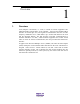
Overview 1. 1 Overview ACS (Adaptive Cell Station, i.e. ACS) is a kind of wireless equipment. The ADPCM signals from the RPC ACS controller enter into the standard 2B+D interface via twisted pair wire; The signals are transmitted in the form of radio frequency modulation wave, which makes up a wireless link between the ACS and PS (Personal Station). The link provides voice/data communications to terminal subscribers via RPC, central terminal equipment and central switch office.
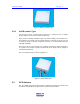
ACS Type 2. 2 ACS Type In terms of the installation environment, ACSs are sorted into Indoor ones and Outdoor ones. 2.1 Indoor ACS Indoor ACS is installed in the wall and ceiling of the place like hotel, government building, bank. It provides the services of PS, telephone and data terminal in the building. It has two antennas that are connected with the main body. The indoor ACS is shown in Figure 2-1. Figure 2-1 indoor ACS 2.
ACS User Guide ACS Type ii Figure 2-2 Singe-ACS outdoor type 2.2.2 4-ACS outdoor Type For this type of ACS, 4 single-ACSs are placed in a waterproof case. It adopts group control mode as well as 4-antennae diversity. These ACSs are usually installed on pole, top of the building. The antennae of 4ACS outdoor are generally placed at high positions, so that the coverage area can be relatively larger. It is also waterproof, need not to be maintained which has with high reliability.
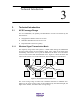
Technical Introduction 3. Technical Introduction 3.1 ACS Coverage Range 3 For ACS installation, the quantity and distribution of ACSs are affected by the factors below: 3.1.1 z Geographical condition of the service area z Subscriber distribution in the service area z Expected traffic and service quality Wireless Signal Transmission Mode The frequency range of the PAS system is 1.
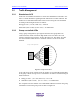
40mW ACS User Guide 3.1.2 Technical Introduction ii Micro-zone Overlap The service will be the best if ACSs are installed as per the micro-zone overlap structure. 2 Km 3.5-5 Km 5.5 -7 Km About 14Km Figure3-2 Coverage Area in Micro-zone Overlap Structure The application of micro-zone overlap and dynamic channel allocation makes the system more flexible and enlarges the system capacity.
40mW ACS User Guide Technical Introduction iii 3.2 Traffic Management 3.2.1 Stand-alone ACS In the case of an isolated ACS there are 4 time slots installed for radio links. One slot is a control channel for signaling and the other three are traffic channels. The number of accommodated subscribers in that ACS covering the zone calculated according to the Erlang-B model is as follows: Erlang per zone: (3 T-chs, GOS=5%) = 0.899 Er Subscribers (FSU or PSs): (0.899 ÷ 0.05) = 18 Subscribers 3.2.
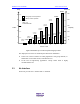
40mW ACS User Guide Technical Introduction iv Subscribers Erlang 25.723(erl) 515 Subs. 500 25 21.094(erl) 422 Subs. £ ºNon-group Control Operation £ ºGroup Control Operation 20 400 18.08(erl) 361 Subs. Note£ º GOS = 5% 0.05Er/Subscriber 14.31(erl) 286 Subs. 15 300 Traffic Capacity 10.633(erl) 213 Subs. 10 200 7.076(erl) 141 Subs 5 3.988(erl) 80 Subs 2.697(erl) 54 Subs 1.798(erl) 0.899(erl) 36 Subs 18 Subs 4.495(erl) 90 Subs. 5.394(erl) 108 Subs. 6.293(erl) 126 Subs. 7.197(erl) 144 Subs.
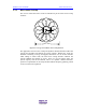
40mW ACS User Guide Technical Introduction v TDMA-TDD Frame (5ms) CS Transmission CS CCH PHS PS #1 CCH PHS PS #2 T2 PHS PS Transmission T4 R2 R2 CCH R2 R2 R4 R4 T2 PHS PS #3 R4 CCH: signaling channel T2,T4: communication channel (to transmit) R2,R4: communication chanenl (to receive) PAS Handset #1: signaling channel, waiting nd PAS Handset #2: 2 time slot, calling th PAS Handset #3: 4 time slot, calling T4 : transmission time slot : receiving time slot : idle time slot Figure3-5 Wireless
40mW ACS User Guide Technical Introduction vi the occupied channel, ACS will appropriately assign the new voice channels. The unoccupied channels and channels with low signal strength are preferred to be taken as the new voice channels. Thus, the newly built WIRELESS LOCAL LOOP system will not affect the normal running of other systems. Moreover, the new system can easily come into use, so that the limited WIRELESS LOCAL LOOP frequency resources can be exploit scientifically and reasonably.
Technical Specifications 4. 4 Technical Specifications Table4-1 Indoor ACS Technical Specifications Item Specifications RF average output power 40mW (peak 230mW) Modulation Pi/4 QPSK Frequency 1880.15 MHz --- 1909.85 MHz Dynamic sensitivity ≤-97dBm Antenna (diversity) Indoor antenna (2 branches) 2.14dBi Air interface Based on RCR STD-28 release 2/3.3 RPC interface 2B+D Voice encoding rate 32kbit/s (ADPCM) Maximum connection length from RPC to ACS 3.5 km(φ0.4mm) Power 4W 5 km (φ0.
40mW CS User Manual Technical Specifications ii Item Specifications Maximum connection length from RPC to ACS 3.5 km(φ0.4mm) Power 4W 5 km (φ0.5mm) Operating requirements Temperature -10°C∼50°C Humidity <95% (no condensing) US Federal Communications Commission (FCC) Warnings: This equipment has been tested and found to comply with the limits for a Class A digital device, pursuant to Part 15 of the FCC Rules.