
User Manual
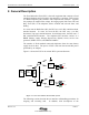
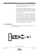
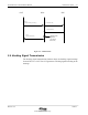
Table Of Contents

Fixed Subscriber Unit Installation Manual General Description
Release 1.00 10/03/97
Airstar-Wireless Local Loop
2-5
3. The RP resends the received message to the Radio Port
Controller (RPC) through the twisted pair wires via the
Main Distribution Frame (MDF).
4. The RPC converts the PHS protocol message to a Q.931
protocol message. In addition, the RPC extracts the dial
code from the outgoing message, and changes it to DTMF
signals. The Q.931 message is sent to the COT through the
D-channel of the E1 line.
5. When the COT receives the outgoing message, it converts
that message, selects and seizes the corresponding analog
line interface to the CO, and returns the seized message to
the RPC. The RPC sends the DTMF dialing signals to the
CO Switch through the voice path via the MDF. After
dialing, the RPC and RP connect all voice paths between
the CO Switch and the FSU connected to the outgoing
standard telephone. The destination telephone rings and is
picked up, and the outgoing call is put through. A voice
path is now established between the 2 telephones.
2.2 Incoming Call
The call handling procedure for an incoming call is depicted in Figure 2-3 and
is described following the figure.
FSU
5
CO COT
RPC
RP
RP
3
2
1
3
4
Switch
MDF
MDF
Figure 2-3 : Incoming Calls