
User Manual

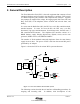
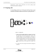
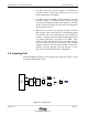
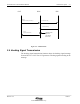

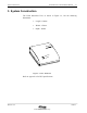

Table Of Contents

Fixed Subscriber Unit Installation Manual General Description
Release 1.00 10/03/97
Airstar-Wireless Local Loop
2-3
2. General Description
The Fixed Subscriber Unit (FSU) is the radio equipment that connects to fixed
standard telephones and is located in the subscriber’s residence. FSUs consist
of a Radio Frequency (RF) interface and a telephone line interface. Together
they manage the supplied line voltage, the ringing signal, Dial Tone (DT) and
Busy Tone (BT) to the telephone, detect off-hook and on-hook states, and
dialing.
In a zone near the Radio Port (RP), the FSU uses a 4.5 dBi, omni-directional,
attached antenna. In zones far from the RP, the FSU uses a 10 dBi,
directional, Yagi type, attached antenna. In mid-range zones, the FSU uses a 7
dBi omni-directional antenna. The telephone line interface consists of a
BRSH (Battery supply, Ringing Supervision, Hybrid) circuit, service tone
generator, DTMF receiver, and ADPCM CODEC.
The number of fixed standard connected telephones from the same battery
supply circuit is three. The power of FSU is fed from the external DC power
generated by AC adapter.
Figure 2-1 shows the FSU in the Airstar-WLL system architecture.
Phone
FAX
Computer
Modem
Fixed
Ssubscriber
Unit
Phone
FAX
Computer
Modem
Indoor RP
Outdoor RP
Radio
Port
Controller
Up to 32
Copper Pair
Up to 5Km
Copper Pair
Up to 5Km
…..
…..
…..
Personal
Station
Air Interface
RCR STD-28
Main
Distribution
Frame
Central
Office
Terminal
4 E1s
…..
…..
…..
Personal
Station
Fixed
Ssubscriber
Unit
Figure 2-1 : Overview of FSU in Airstar-WLL System
The following sections describe the air interface call handling procedures for
outgoing and incoming calls. In addition, brief descriptions of the