Introduction to This Manual Fixed Subscriber Unit Installation Manual 1-1 1. Introduction to This Manual This manual contains all the information necessary to install and maintain the Fixed Subscriber Unit (FSU). 1.1 Organization This manual is organized to assist the installer and technician in gaining an understanding of the Fixed Subscriber Unit in terms of the system’s physical characteristics, installation instructions, and maintenance methods.
1-2 Introduction to This Manual Fixed Subscriber Unit Installation Manual 10/03/97 Release 1.
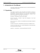
Fixed Subscriber Unit Installation Manual General Description 2-3 2. General Description The Fixed Subscriber Unit (FSU) is the radio equipment that connects to fixed standard telephones and is located in the subscriber’s residence. FSUs consist of a Radio Frequency (RF) interface and a telephone line interface. Together they manage the supplied line voltage, the ringing signal, Dial Tone (DT) and Busy Tone (BT) to the telephone, detect off-hook and on-hook states, and dialing.
2-4 General Description Fixed Subscriber Unit Installation Manual authentication, hooking signal transmission, and meter pulsing signal transmission functions are provided. 2.1 Outgoing calls The call handling procedure for an outgoing call is depicted in Figure 2-2 and is described following the figure. A terminal on an FSU sends dialing information with standard in-band DTMF tones after recognizing dial tone. 5 CO Switch MDF 4 COT RPC 3 RP 1 2 MDF FSU RP 3 Figure 2-2 : Outgoing Call 1.
Fixed Subscriber Unit Installation Manual General Description 2-5 3. The RP resends the received message to the Radio Port Controller (RPC) through the twisted pair wires via the Main Distribution Frame (MDF). 4. The RPC converts the PHS protocol message to a Q.931 protocol message. In addition, the RPC extracts the dial code from the outgoing message, and changes it to DTMF signals. The Q.931 message is sent to the COT through the D-channel of the E1 line. 5.
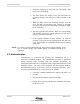
2-6 General Description Fixed Subscriber Unit Installation Manual 1. A specific analog line is rung in the CO. The signal is sent to the COT via the MDF. 2. The COT detects the ringing of the line and sends the incoming message with the Q.931 calling number to the RPC. 3. When the RPC receives the incoming message from the COT, the RPC converts that Q.931 message to the PHS incoming message protocol and sends it through the MDF to all of the RPs. 4. The RPs page all FSUs and PSs.
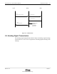
Fixed Subscriber Unit Installation Manual General Description COT RPC Facility (Authentication Required (Key)) 2-7 FSU Authentication Req Authentication Req Facility (Authentication Result) Authentication operation (calculation and check) Figure 2-4 : Authentication 2.4 Hooking Signal Transmission The hooking signal transmission function relays the hooking signal message from an FSU to a COT. The COT generates a hooking signal according to the message. Release 1.
2-8 System Construction Fixed Subscriber Unit Installation Manual 10/03/97 Release 1.
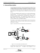
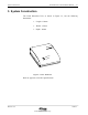
System Construction Fixed Subscriber Unit Installation Manual 3-9 3. System Construction The Fixed Subscriber Unit, as shown in Figure 3-1, has the following dimensions: • Length : 130mm • Width : 175mm • Depth : 40mm rcom UTSta ITOR MON ER POW Figure 3-1 : FSU - Main Unit Refer to Appendix A for FSU specifications. Release 1.
3-10 Installation Instructions Fixed Subscriber Unit Installation Manual 09/06/2001 Release 2.
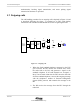
Fixed Subscriber Unit Installation Manual Installation Instructions 4-11 4. Installation Instructions This section provides instructions for installing an FSU. The flow-chart in Figure 4-1 defines the steps involved in an installation. Begin Install Antenna Preparation Choose Antenna Location Install Coaxial Cable Choose Main Unit Location Install Main Unit Gather Accessories and Tools Adjust Antenna Configure FSU End Figure 4-1 : FSU Installation Flow Chart 4.
4-12 Installation Instructions Fixed Subscriber Unit Installation Manual 4.1.1 Plan FSU Configuration The FSU must be configured at subscription time with the subscriber’s telephone number, authentication key, operator ID, and carrier channel. The subscriber’s data must also be entered into the COT. The following data must be entered for each subscriber: • Telephone number • Authentication key • FXO port RP numbers of the RPs having the control channel for each FSU must also be entered in the COT.
Fixed Subscriber Unit Installation Manual Installation Instructions 4-13 • On a wall or pole that is sufficiently strong, make sure wall or pole can withstand winds common to the area • Away from other objects such as poles, trees, buildings, and so on that block the signal from the Radio Port; in general the minimum distance is 750 mm. 4.1.3 Antenna Type Determination Guidelines The Coverage Map shows Radio Port locations and the area covered by the RP.
4-14 Installation Instructions Fixed Subscriber Unit Installation Manual between the main unit and the antenna, position the indoor main unit as close as possible to the outdoor antenna. Note : Make sure that the FSU Main Unit is positioned so that the green LEDs are visible to the subscriber. When reporting trouble, the subscriber will be asked the status of the LEDs. 4.1.5 Installation Accessories, Standard and Special Tools This section lists all the equipment needed for and FSU installation.
Fixed Subscriber Unit Installation Manual Installation Instructions 4-15 • Phillips (or Plus) screwdriver • Electric drill • Step ladder • AC power extension cord Special Tools for Cable Termination: • Cable stripper • Crimper Antenna Orientation Instruments: • Map • Compass • Binoculars Measuring Receiver or Equivalent: • Measuring receiver • Memory card • AC adapter • Adapter (3-poles→2-poles conversion) • Coaxial cable adapter TNC-J/SM-J (optional) • 5 meters of coaxial cab
4-16 Installation Instructions Fixed Subscriber Unit Installation Manual • Authentication key • Operator ID • Control carrier The above data is entered using the PSJ_Jr. device connected to a PC that has been loaded with the FSUJ software. Note : The FSUJ screens shown in this section are presented in inverse black and white for clarity. WARNING : MAKE SURE THAT THE FSU’S CONFIGURATION DATA IS READ PRIOR TO WRITING THE NEW CONFIGURATION DATA.
Fixed Subscriber Unit Installation Manual Installation Instructions 4-17 Figure 4-2 : FSUJ Menu 5. Use the ↓ key to move the cursor to the WLLSO Setup option and press the Enter ↵ key. This displays a WLLSO Setup screen similar to the one shown in Figure 4-3. Figure 4-3 : WLLSO Setup Screen Without Configuration Data 6. To read the factory configured data, press the F2 key. On the screen, this key is labeled E2read. Release 1.
4-18 Installation Instructions Fixed Subscriber Unit Installation Manual 7. A confirmation box appears prompting execute to read to E2PROM. OK (Y/N). Enter Y. The screen is populated with the factory configured data. Refer to Figure 4-4. Figure 4-4 : WLLSO Setup Screen With Configuration Data Note : This application uses the letter A for zero. Zero is used for a delimiter. 8.
Fixed Subscriber Unit Installation Manual Installation Instructions 4-19 4.3 Coaxial Cable Installation Once the locations for the antenna and the main unit have been determined, use the procedures in this section to install the cable. 1. Measure and cut a length of cable to fit between the main unit and the antenna. 2. Run the cable between the main unit and the antenna. 3. Using the cable stripper, strip both ends of the coaxial cable. Refer to the figure below for exact dimensions to strip.
4-20 Installation Instructions Fixed Subscriber Unit Installation Manual 4.4 Antenna Installation NOTE : The antenna shown in this manual is one of the three types of antennae used in the Airstar-WLL system. 1. Unpack the FSU Antenna and accessories. Make sure all parts are in good condition. The FSU Antenna and accessories are shown in Figure 4-6.
Fixed Subscriber Unit Installation Manual Installation Instructions 4-21 2. Assemble the FSU antenna by attaching the bracket to the antenna according to Figure 4-7. Figure 4-7 : Antenna Bracket Assembly 3. After installing the antenna, use the PHS Signal Analyzer to check the receiving signal level. Measure the reception level (RX LVL) at the TNC connector on the FSU. Target values are as follows : • RX LVL: more than -78dBm (35dBµV) • Frame Error Rate: less than 2% Release 1.
4-22 Installation Instructions Fixed Subscriber Unit Installation Manual 4. At the site selected for the FSU antenna, tentatively mount the antenna and take several RSS measurements approximately 15 cm from the antenna. Position the antenna where it receives that strongest signal. Then mount the antenna on a pole.
Fixed Subscriber Unit Installation Manual Installation Instructions 4-23 WARNING : DEPENDING ON LOCATION, IT MAY BE NECESSARY TO GROUND THE ANTENNA TO PREVENT DAMAGE BY LIGHTNING. REFER TO THE FIGURE BELOW FOR A DIAGRAM OF THE EARTH CABLE CONNECTION. 6 inches above ground Terminal Lug ground line AWG 12 copper wire insulated 5 ft. by .5 inch copper clad rod Figure 4-9 : Earth Cable Connection 6. Attach a terminal lug to the lower bracket screw and tighten screw. 7.
4-24 Installation Instructions Fixed Subscriber Unit Installation Manual 9. Connect the coaxial cable to the antenna as shown in Figure 4-10. Coaxial Cable Figure 4-10 : Coaxial Cable Connection to Antenna 10. Wrap the cable connection first with the self-adhesive rubber tape. Stretch the tape until it is ½ its original width. Then wrap the PVC tape around the rubber tape. 4.5 Main Unit Installation Follow the steps below to install the FSU Main Unit in the subscriber’s residence. 1.
Fixed Subscriber Unit Installation Manual Installation Instructions 4-25 Main Unit Connector Cover Figure 4-11 : FSU and Accessories Release 1.
4-26 Installation Instructions Fixed Subscriber Unit Installation Manual 2. Connect the external antenna cable to the Antenna Cable Outlet located on the back of the FSU. Refer to Figure 4-12. Connector Cover Figure 4-12 : Antenna Cable Connection 09/06/2001 Release 2.
Fixed Subscriber Unit Installation Manual Installation Instructions 4-27 3. Connect the telephone set to the RJ-11 jack on the back of the FSU using a standard telephone cord. See Figure 4-13. Figure 4-13 : Telephone Cord Connection Note : The telephone cord must have an RJ-11 type plug. Release 1.
4-28 Installation Instructions Fixed Subscriber Unit Installation Manual 4. Connect the Backup Battery Unit to the DC Input receptacle, also on the back of the FSU. NOTE : A fully charged backup battery allows the FSU to continue operation if power fails. The backup battery provides approximately two hours of talking time and approximately 20 hours of standby time. Recharging may take up to 30 hours.
Fixed Subscriber Unit Installation Manual Installation Instructions 4-29 5. Connect the AC/DC Adapter to the Backup Battery Unit, as shown in the figure below. Figure 4-15 : AC/DC Adapter Connection Release 1.
4-30 Installation Instructions Fixed Subscriber Unit Installation Manual 6. Connect the AC/DC Adapter to an AC outlet. Refer to Figure 4-16. The Monitor Lamp on the FSU should light, indicating the line is ready for use. If the Monitor Lamp blinks or does not light, adjust the antenna until the Monitor Lamp remains lit. If the Monitor Lamp does not light after antenna adjustment, contact a qualified service technician. Figure 4-16 : AC Outlet Connection 09/06/2001 Release 2.
Fixed Subscriber Unit Installation Manual Installation Instructions 4-31 7. If wall mounting is desired, locate a position on the wall for the FSU. Mark the screws’ locations using the enclosed mounting template. Mount the main unit on the wall using the supplied two screws. Refer to Figure 4-17. 84 mm Figure 4-17 : Wall Mounting 8.
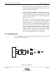
4-32 Installation Instructions Fixed Subscriber Unit Installation Manual Figure 4-18 depicts an FSU configuration in a subscriber’s residence. FSU Standard Telephone Connector RF Interface Telephone Line Interface Battery AC Adapter To AC Outlet Figure 4-18 : Fixed Subscriber Unit Configuration 09/06/2001 Release 2.
Fixed Subscriber Unit Installation Manual Acronym and Abbreviation List 5-33 5.
5-34 Acronym and Abbreviation List Fixed Subscriber Unit Installation Manual 09/06/2001 Release 2.