Utility Trailer Owner’s Manual ^ WARNING This Owner’s Manual contains safety information and instructions for your trailer. You must read this manual before loading or towing your trailer. You must follow all safety precautions and instructions. Rockford Commercial Warehouse 8105 Burden Rd.
Contents 1. Introduction........................................................................................... 5 2. Safety .................................................................................................... 6 2.1 Safety Alert Symbols And Signal Words .......................................................6 2.2 Major Hazards ...................................................................................................6 2.2.1 Improper Sizing Of Trailer To Tow Vehicle ...............
Contents 4. Coupling To Tow Vehicle ................................................................... 26 4.1 Tow Vehicle And Hitch ...................................................................................26 4.1.1 Trailer Information ...................................................................................................... 26 4.1.2 Tow Vehicle ................................................................................................................. 26 4.
7. Breaking In A New Trailer .................................................................. 41 7.1 Retighten Lugs At First 10, 25 & 50 Miles....................................................41 7.2 Adjust Brake At First 200 Miles ....................................................................41 7.3 Synchronizing Brake Systems .....................................................................41 8. Accessories ......................................................................................
Introduction 1. Introduction Congratulations on the purchase of your trailer. We believe you will be happy and completely satisfied with your purchase. Our goal is to provide a valued customer a quality trailer at a reasonable price. For your safety, read and understand this manual before operating your trailer. If there are any questions about information in this manual, please consult your dealer. When calling about your trailer, please have the VIN number available for the dealer.
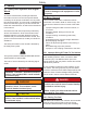
Safety 2. Safety NOTICE 2.1 Safety Alert Symbols And Signal Words NOTICE - Indicates a situation that could result in damage to the equipment or other property. An Owner’s Manual that provides general trailer information cannot cover all of the specific details necessary for the proper combination of every trailer, tow vehicle and hitch. You must read, understand and follow the instructions given by the tow vehicle and trailer hitch manufacturers, as well as the instructions in this manual. 2.
Safety 2.2.4 Trailer Not Properly Coupled To Hitch the possibility for loss of control. Also your tires may overheat, increasing the possibility of a blowout. It is critical that the trailer be securely coupled to the hitch, and that the safety chains and emergency breakaway brake lanyard are correctly attached. Uncoupling may result in death or serious injury to you and to others. ^ WARNING Driving too fast for conditions can result in loss of control and cause death or serious injury.
Safety 2.2.7 Matching Trailer And Hitch 2.2.5 Proper Use Of Safety Chains Safety chains are provided so that control of the trailer can be maintained if your trailer comes loose from the hitch. ^ DANGER Be sure hitch and tow vehicle are rated for the Gross Vehicle Weight Rating (GVWR) of your trailer. ^ WARNING Improper rigging of the safety chains can result in loss of control of the trailer and tow vehicle, leading to death or serious injury, if the trailer uncouples from the tow vehicle.
Safety ^ WARNING ^ WARNING Inflate tires to pressure stated on the Certification / VIN label. Wheel nuts or bolts are prone to loosen after being first assembled. Death or serious injury can result. Improper tire pressure may cause unstable trailer. Blowout and loss of control may occur. Death or serious injury can result. Check wheel nuts or bolts for tightness on a new trailer, and after re-mounting a wheel at 10, 25 and 50 miles. Make sure of proper tire pressure before towing trailer.
Safety 2.2.10 Unsafe Load Distribution ^ WARNING Improper front/rear load distribution can lead to an unstable trailer or poor tow vehicle handling. Poor trailer stability results from tongue weights that are too low, and poor tow vehicle stability results from tongue weights that are too high. Improper tongue weight (load distribution) can result in loss of control of the trailer, leading to death or serious injury. Make certain that tongue weight is within the allowable range.
Safety 2.2.14 Trailer Modifications ^ WARNING Do not transport flammable, explosive, poisonous or other dangerous materials on your trailer. Modification of the trailer structure or alteration of your trailer can make the trailer unsafe and will void all warranty options. Before making any alteration to the trailer, contact your dealer or the manufacturer and describe the alteration you are contemplating. The exception is fuel in the tank of a vehicle or equipment being hauled. 2.2.
Safety Some drivers place their hands at the bottom of the steering wheel, and while the tow vehicle is in reverse, “think” of the hands as being on the top of the wheel. When the hands move to the right (counter-clockwise, as you would do to turn the tow vehicle to the left when moving forward), the rear of the trailer moves to the right. Conversely, rotating the steering wheel clockwise with your hands at the bottom of the wheel will move the rear of the trailer to the left, while backing up.
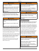
Safety 2.2.17 Safety Warning Labels On Your Trailer Depending on trailer configuration, your trailer may not be equipped with all safety labels shown.
Safety 14
Safety ^ WARNING To protect you and others against death or serious injury, all applicable labels shown must be on the trailer and must be legible. If any of these labels are missing or cannot be read, contact your dealer for replacement labels.
Safety 2.2.18 Reporting Safety Defects If you believe that your vehicle has a defect that could cause a crash or could cause injury or death, you should immediately inform the National Highway Traffic Safety Administration (NHTSA) in addition to notifying Rockford Commercial Warehouse If NHTSA receives similar complaints, it may open an investigation, and if it finds that a safety defect exists in a group of vehicles, it may order a recall and remedy campaign.
Tire Safety 3. Tire Safety Information 3.1 Trailer Tire Information This portion of the User’s Manual contains tire safety information as required by 49 CFR 575.6. Trailer tires may be worn out even though they still have plenty of tread left. This is because trailer tires have to carry a lot of weight all the time, even when not in use. Section 3.1 contains “Trailer Tire Information”. It is actually better for the tire to be rolling down the road than to be idle.
Tire Safety out and should be replaced, even if they have had minimal or no use. This is such a general statement that it may not apply in all cases. It is best to have your tires inspected by a tire supplier to determine if your tires need to be replaced. occurs. This situation can generate an excessive amount of heat within the tire. Excessive heat may lead to tire failure. It is the air pressure that enables a tire to support the load, so proper inflation is critical.
Tire Safety 3.3 Steps For Determining Correct Load Limit - Tow Vehicle Cold inflation pressure: The pressure in the tire before you drive. Cord: The strands forming the plies in the tire. 1. Locate the statement, “The combined weight of 2. 3. 4. 5. 6. occupants and cargo should never exceed XXX lbs.,” on your vehicle’s placard. Determine the combined weight of the driver and passengers who will be riding in your vehicle.
Tire Safety sidewall of the tire or the outward facing sidewall of an asymmetrical tire that has a particular side that must always face outward when mounted on a vehicle. Occupant distribution: The distribution of occupants in a vehicle as specified in the third column of Table I of 49 CFR 571.110. Light truck (LT) tire: A tire designated by its manufacturer as primarily intended for use on lightweight trucks or multipurpose passenger vehicles. May be used on trailers.
Tire Safety Rim diameter: This means the nominal diameter of the bead seat. axle its share of the curb weight, accessory weight, and normal occupant weight (distributed in accordance with Table I of CRF 49 571.110) and dividing by 2. Rim size designation: This means the rim diameter and width. Weather side: The surface area of the rim not covered by the inflated tire. Rim type designation: This means the industry of manufacturer’s designation for a rim by style or code.
Tire Safety • • Fundamental characteristics of tires Tire safety tips. load limit, that is, the greatest amount of weight a vehicle can safely carry and the vehicle’s tire size. The proper tire pressure for your vehicle is referred to as the “recommended cold inflation pressure.” (As you will read below, it is difficult to obtain the recommended tire pressure if your tires are not cold.) Use this information to make tire safety a regular part of your vehicle maintenance routine.
Tire Safety 5. At a service station, add the missing pounds of air correctly relative to the vehicle’s frame. This adjustment maximizes the life of your tires. These adjustments require special equipment and should be performed by a qualified technician. pressure to each tire that is under inflated. 6. Check all the tires to make sure they have the same air pressure except in cases in which the front and rear tires are supposed to have different amounts of pressure). 3.5.
Tire Safety for improved steering response and better overall handling on dry pavement. R: The “R” stands for radial. Radial ply construction of tires has been the industry standard for the past 20 years. Maximum Permissible Inflation Pressure: This number is the greatest amount of air pressure that should ever be put in the tire under normal driving conditions. 3.5.10.2 UTQGS Information Next number: This two-digit number is the wheel or rim diameter in inches.
Tire Safety ST: An “ST” is an indication the tire is for trailer use only. Max. Load Dual kg (lbs) at kPa (psi) Cold: This information indicates the maximum load and tire pressure when the tire is used as a dual, that is, when four tires are put on each rear axle (a total of six or more tires on the vehicle). Max. Load Single kg (lbs) at kPa (psi) Cold: This information indicates the maximum load and tire pressure when the tire is used as a single.
Coupling To Tow Vehicle 4. Coupling To Tow Vehicle the lowest of axle, wheel, or tire rating. Sometimes the tire or wheel rating is lower than the axle manufacturers rating, and will then determine GAWR. Follow all of the safety precautions and instructions in this manual to ensure safety of persons, cargo, and satisfactory life of the trailer.
Coupling To Tow Vehicle Hitch: The connecting mechanism including the ball support platform and ball and those components that extend and are attached to the towing vehicle, including bumpers intended to serve as hitches. ^ WARNING An improperly coupled trailer can result in death or serious injury. Do not move the trailer until: Safety chains: Chains permanently attached to the trailer such that if the coupler connection comes loose, the safety chains can keep the trailer attached to the tow vehicle.
Coupling To Tow Vehicle 4.3.1.1 Before Coupling Trailer To Tow Vehicle 6. Raise the bottom surface of the coupler to be above the top of the hitch ball. 1. Be sure the size and rating of hitch ball match the size and rating of the coupler. Hitch balls and couplers are marked with their size and rating. 4.3.1.2 PREPARE COUPLER AND HITCH 1. Lubricate hitch ball and inside of coupler with a thin layer of automotive bearing grease. ^ WARNING 2.
Coupling To Tow Vehicle 6. Lower the trailer so that its entire tongue weight is ^ WARNING held by the hitch, and continue retracting the jack to its fully retraced position. Ring-to-pintle mismatch can result in uncoupling, leading to death or serious injury. ^ CAUTION Drop leg jacks may be spring loaded and may rapidly return to the raise position when released. Be sure the LOAD RATING of the pintle is equal or greater than the load rating of the ring. Keep clear when releasing drop legs.
Coupling To Tow Vehicle 3. In the open position, the ring is able to drop fully 7. Fully retract jack drop leg if equipped. onto the pintle. Go to Section 4.3.3 “Connect Safety Chains” to continue connecting trailer to tow vehicle. 4.3.3 Connect Safety Chains 1. Visually inspect the safety chains and hooks for wear or damage. Replace worn or damaged safety chains and hooks before towing. 2.
Coupling To Tow Vehicle hydraulic actuator will engage or the electric brake pullpin will be pulled out before all of the slack in the safety chains is taken up. Do not connect the lanyard to a safety chain, hitch ball or hitch ball assembly. This would keep the breakaway brake system from operating when it is needed.
Coupling To Tow Vehicle Most trailers are setup to charge the battery from the tow vehicle. If the electrical system on your tow vehicle does not provide power to the battery, you must periodically charge the battery with a commercial battery charger to keep the battery charged. ^ WARNING Failure to replace the pullpin can result in ineffective brakes, leading to loss of control, serious injury or death.
Coupling To Tow Vehicle The board should be 4 feet or longer so it will extend several feet above the actuator. Keep the end of the board a few inches off the ground, and position it to press against the front end of the actuator’s coupler. Press the board towards the rear of the trailer. 1. Park the trailer on a firm level surface and block trailer tires. Disconnect electrical connector. Disconnect breakaway brake switch lanyard. Disconnect safety chains from tow vehicle. Unlock the coupler and open it.
Coupling To Tow Vehicle 4.6 Adjust Hitch Height (If Equipped) The numbers quoted are for example purposes only and should be tailored to the specific trailer. The height of the hitch on the trailer must be adjusted so that the trailer, when loaded to rated capacity, is level while connected to the tow vehicle. A level trailer allows equal weight distribution on the axles. For questions regarding the actual percent of tongue weight for the trailer, check with the manufacturer for specifics.
Coupling To Tow Vehicle ^ WARNING Used lock nuts are prone to loosen, resulting in the hitch separating from the trailer, which can lead to death or serious injury. NEVER re-use a lock nut. Use new lock nuts each time the hitch height is adjusted. Contact your dealer for the proper grade and size of lock nut. 6. Raise or lower the hitch as necessary. 7. Install bolts and new lock nuts. 8. Tighten lock nuts to torque specified by your dealer. 9.
Loading And Unloading 5. LOADING AND UNLOADING ^ WARNING Improper trailer loading causes many accidents and deaths. To safely load a trailer, you must consider: • Overall load weight. • Load weight distribution. • Proper tongue weight. • Securing the load properly. Do not transport people on your trailer. Besides putting their lives at risk, the transport of people on a trailer is illegal. 5.
Loading And Unloading ^ CAUTION ^ WARNING Use a safe lifting procedure to avoid injury when handling ramps. Loading a pivoting-deck trailer before retracting the deck catch pin can crack the catch pin, which can cause loss of cargo or loss of control of the trailer. Death or serious injury may result. 3. Remove ramps from storage position and secure to rear of trailer. Adjust ramp position to align with equipment tires or tracks. Before loading the trailer, retract the deck catch pin.
Loading And Unloading 5.1.3.2 Hydraulic Tilt Trailer 5. Release deck latch pin to pivot trailer deck for unloading. 1. Couple the trailer to the tow vehicle. ^ WARNING ^ WARNING Unloading a pivoting-deck trailer before retracting the deck catch pin can crack the catch pin, which can cause loss of cargo or loss of control of the trailer. Death or serious injury may result. Trailer must be coupled to tow vehicle before loading trailer. 2.
Loading And Unloading procedure before operating the tilt deck. 6. Locate the tilt deck controller. Position yourself in a safe location clear of the tilt deck. 7. Press and hold button to raise the tilt deck. Release the button when the rear of the tilt deck touches the ground. 8. Unload the cargo from trailer. 9. Press and hold button to lower the tilt deck. Release the button when the tilt deck is in the driving position. 10. Stow controller. 5.
Pre-Tow Checklist 6. Pre-Tow Checklist 6.1 Pre-Tow Checklist Before towing, double-check all of these items: • Tires, wheels and lug nuts. See “Breaking In A New Trailer” section of this manual. • Tire Pressure. Inflate tires on trailer and tow vehicle to the pressure stated on the Certification / VIN label. • Coupler secured and locked. See “Coupling To Tow Vehicle” section of this manual. • Safety chains properly rigged to tow vehicle, not to hitch or ball.
Breaking In A New Trailer 7. Breaking In A New Trailer ^ WARNING If trailer and tow vehicle brakes do not work properly together, death or serious injury can occur. 7.1 Retighten Lugs At First 10, 25 & 50 Miles Wheel lugs can shift and settle quickly after being first assembled, and must be checked after the first 10, 25 and 50 miles of driving. Failure to perform this check may result in a wheel coming loose from the trailer, causing a crash leading to death or serious injury.
Accessories 8. Accessories This section provides some basic information for the safe operation of accessories. You must read and follow these instructions before using the accessory. If you are uncertain whether you have all of the instructions, contact your dealer before operating the accessory. 8.1 Accessory Battery Your trailer may be equipped with an accessory battery that operates the tilt deck.
Inspection, Service And Maintenance 9. Inspection, Service And Maintenance 9.1 Inspection, Service & Maintenance Summary Charts You must inspect, maintain and service your trailer regularly to insure safe and reliable operation. If you cannot or are unsure how to perform the items listed here, have your dealer do them. Note: In addition to this manual, also check the relevant component manufacturer’s manual.
Inspection, Service And Maintenance Inspection And Service Every Month Inspection / Service Manual Section Reference Lubricate tilt deck pivot points (if Section 9. equipped). Item Lubrication Lubricate hydraulic cylinder ends (if Section 9. equipped). Item Brakes, electric • Magnet • Inspection and Service Every 6 Months or 6,000 Miles Inspection/Service Manual Section Reference Controller (in tow vehicle) Tires Check wear and current draw. Section 9. Check power output (amperage) Section 9.
Inspection, Service And Maintenance Item Brakes, all types • Shoes and Drums Inspection And Service Every Year or 12,000 Miles Inspection/Service Manual Section Reference Check for scoring and wear. Replace Section 9. per manufacturer’s specifications. See Brake Mfr’s Manual Jack, Drop-leg (if equipped) Structure • Frame Members • Welds Wheels Wheel Bearings • • Grease gears at top. See Jack Mfr’s Manual Inspect all frame members, bolts & Section 9. rivets.
Inspection, Service And Maintenance 9.2 Inspection And Service Instructions ^ WARNING ^ WARNING Broken or damaged fasteners can cause injury or damage to trailer and contents. Worn or broken suspension parts can cause loss of control and injury may result. Inspect for, and repair all damaged parts at least once a year. Have trailer professionally inspected annually and after any impact. 9.2.1.2 Welds To perform many of the inspection and maintenance activities, you must jack up the trailer.
Inspection, Service And Maintenance is “hard braked” from a rearward direction. Read your axle and brake manual to see how to adjust your brakes. If you do not have this manual, contact your dealer for assistance. ^ CAUTION Extreme cold weather can degrade battery performance and cause brakes to not operate properly. 9.2.2.2 Manually Adjusting Brake Shoes Some braking systems are not automatically adjusted. These brakes require manual adjustment.
Inspection, Service And Maintenance reservoir. Check with your dealer for the type of brake fluid used in the brake system. trailer has multiple axles, bleed the rear axle first. Submerse the other end of the hose in a glass container of brake fluid, so that air bubbles can be observed. 4. Open the bleeder screw and have an assistant stroke (but not release) the actuator. Brake fluid and/or air bubbles will flow into the jar. Close the bleeder screw.
Inspection, Service And Maintenance 9.2.7 Wheel Rims The coupler latch lever must be able to rotate freely and automatically snap into the latched position. Oil the pivot points, sliding surfaces, and spring ends with SAE 30W motor oil. Keep the ball pocket and latch mechanism clean. Dirt or contamination can prevent proper operation of the latching mechanism. If the trailer has been struck, or impacted, on or near the wheels, or if the trailer has struck a curb, inspect the rims for damage.
Inspection, Service And Maintenance If your axle(s) are equipped with a grease zerk on the ends of the axle(s), the bearings must be greased every 6 months or 6,000 miles to ensure reliable and safe operation of your trailer. 1. Remove the rubber plug from the axle end. 2. Place grease gun on zerk. 3. Pump grease until new grease begins to appear. Use a different color grease each time so you will know when the new grease begins to appear. 4. Install rubber plug and cap. Repeat for remaining wheel bearings.
Inspection, Service And Maintenance ^ WARNING Metal creep between the wheel rim and lug nuts or bolts can cause rim to loosen. Death or injury can occur if wheel comes off. Tighten lug nuts or bolts before each tow. Tighten the lug nuts or bolts in three stages to the final torque for the axle size on your trailer, to prevent wheels from coming loose. Tighten each lug nut or bolt in the order shown in the following figure. Use a calibrated torque wrench to tighten the fasteners.
WARRANTY STATEMENT Rockford Commercial Warehouse, Inc. here warrants that each SUPERTEST trailer operated by the original purchaser under normal use in the Continental United States or Canada will be free from defects in materials and workmanship for 90 Days following the original purchase, subject to the requirements exclusions and limitations stated below which will be strictly applied. If the trailer is rented or used for commercial hauling, this Limited Warranty is null and void.
LIMITATIONS THE SOLE RESPONSIBILITY OF ROCKFORD COMMERCIAL WAREHOUSE, INC. UNDER THIS LIMITED WARRANTY SHALL BE TO REPAIR AND REPLACE PARTS AT THE ROCKFORD COMMERCIAL WAREHOUSE, INC. FACTORY OR, FOR A REASONABLE ALLOWANCE, AT ANOTHER PLACE AND PREPARED IN WRITING BY ROCKFORD COMMERCIAL WAREHOUSE, INC.
4. Any defective part(s) must be sent by prepaid freight to Rockford Commercial Warehouse, Inc., in order to qualify the claimant for replacement or reimbursement under this Limited Warranty. ANY DEFECTIVE PARTS MUST BE RETURNED TO ROCKFORD COMMERCIAL WAREHOUSE, INC. WITHIN 30 DAYS FROM DATE OF APPROVAL TO QUALIFY FOR REIMBURSEMENT. 5. Rockford Commercial Warehouse, Inc.
UTILITY DUMP TRAILER KIT ASSEMBLY(GUIDE( Model(STC5806( 2014%STC%Interna/onal.%%All%rights%reserved.
PARTS(LIST( x%1%% x%2%% Side(Wall( Trailer(Frame( x%2%% Drop(Gate( x%2%% (preHassembled(on(Tongue)( x%1%% Axle( x%2%% x%1%% Safety(Chain( (preHassembled(on(Coupler)( x%2%% Slipper(Spring( x%2%% x%2%% Tire/Wheel( Tongue( Fender( 2”(Coupler( x%1%% Rear(Light( (in(LED(Light(Kit)( x%2%% Side(Marker( (in(LED(Light(Kit)( ( *Use%Cau)on%when%li0ing%heavy%parts.%Seek%assistance%when%necessary.
PARTS(LIST( Hardware(Blister(Pack(1( Includes:( ( (1) Pivot(Bolt( ( ( ( (4) Slipper(Spring(Bolts( Hardware(Blister(Pack(2( Includes:( ( (6)(Side(Panel(Bolts( ( ( ( ( ( ( (4)(U(Bolts( ( ( ( ( Tools(Required( Metric%Sockets:%% ?6mm% ?7mm% ?13mm%% ?17mm% ?19mm% ?24mm%% Metric%Wrenches:% ?6mm% ?7mm% ?13mm%% ?17mm%% ?19mm% ?24mm% ( (2)(Fender(Bolts( ( ( ( ( ( ( (4)(Front/Rear(Drop(Gate( Bolts( ( ( ( ( ( ( ?Small%Phillips%screwdriver% ?Adjustable%Wrench% % 2%
Assembly(Instruc^ons( ( STEP(1:(READ(OWNERS(MANUAL( Refer%back%to%Manual%for%proper%opera/ng%and%safety%informa/on% regarding%your%new%trailer.%% % STEP(2:%REMOVE(ALL(PARTS% Open%Box%and%carefully%and% remove%ALL%parts.%% % %Use%cau)on%when%li0ing%% %heavy%parts.%Seek%assistance%% %when%necessary. %% % STEP(3:(FLIP(TRAILER(FRAME(OVER( With%help,%place%trailer%frame%with%the%BOTTOM%facing%up,%on%a%% RAISED%Surface%for%assembly.% % Use$cau(on$when$placing$onto$ raised$surface.
STEP(4:(ATTACH(TONGUE(MOUNT(% Lay%the%tongue%into%the%load%bearing%guide% (Make%sure%the%tongue%stand%is%pointed%UP% and%is%out%past%front%of%trailer%frame).%% % % A_ach(Pivot(Bolt(and(Lock(Nut(( to%back%of%tongue%mount%using%% 24mm%ratchet%and%wrench.$ $ *NOTE:$Middle$Bolt$posi(on$should$only$be$$ used$when$tongue$extension$is$required.$ % Connect(the(front(of(tongue(mount( Slide%the%removable%L%Pin%through%the%front%% of%the%tongue%mount%hole%and%tongue%hole.% Then,%secure%the%L%Pin%using%the%coXer%pin.
STEP(6:(SECURE(THE(COUPLER(% % Although%already%aXached%during%% produc/on,%use%19%mm%Ratchet%and%% Wrench%to%make%sure%the%COUPLER%is%% securely%/ghtened%to%the%TONGUE.( % Tools%Needed:%19mm%Ratchet%and%Wrench% % Parts%Needed:%Coupler%(already%aMached%to%TONGUE)% % ( STEP(7:(SECURE(THE(SAFETY(CHAINS( % Use%17mm%Ratchet%and%Wrench%to%make%sure%% the%SAFETY%CHAINS%are%securely%/ghtened%to% the%COUPLER.
STEP(8:(ATTACH(SLIPPER(SPRINGS(% Lay%slipper%springs%in%track%with%the%‘eye’%% facing%towards%the%front%of%the%trailer.% % Use%a%19mm%ratchet%and%wrench%to%aXach%% bolt%through%the%spring%eye%into%the% second%pre?drilled%hole,%towards%rear%of%% frame,%as%shown.%Securely%/ghten.% % Place%second%bolt%through%the%pre?drilled%% hole%in%back%of%the%trailer%frame.%% DO%NOT%TIGHTEN%FULLY.%% You$will$use$this$bolt$in$the$fender$assembly$$ in$STEP$15.% % Repeat(steps(on(opposite(side.
STEP(10:(ATTACH(TIRE(ASSEMBLY( Remove%the%wheel%lug%nuts%from%the%hubs%on%axle.%% Slide%the%wheel%assembly%onto%the%axle,%with% the%Valve%Stems%facing%out.%%% % Replace%the%lug%nuts%with%the%narrow%end% towards%the%inside%of%/re.%Use%torque%wrench%% with%19mm%socket%and%extension%to%secure%% the%lug%nuts.%Secure%onto%the% hubs%with%65?70%d?lb%of%torque.% ( Repeat(steps(on(opposite(side.
STEP(12:(ATTACH(LED(SIDE(MARKERS( Locate%the%wire%harness%for%the%side%marker% lights%on%the%frame%and%plug%into%the%% side%marker%connector.%% % Feed%light%wire%through%pre?drilled%%center%% hole%in%rear%of%frame%and%aXach%light.% % Use%a%small%Phillips%screwdriver%and%7%mm% ratchet%or%wrench%to%aXach%side%markers%to% the%frame.% ( Repeat(steps(on(opposite(side.
STEP(14:(ATTACH(SIDE(PANELS(TO(FRAME( Carefully%place%side%wall%into%slots%on%frame.%% NOTE:$Side$Wall$“POSTS”$should$be$placed$$ on$the$OUTSIDE$of$trailer$bed.$ % Using%13mm%ratchet%and%wrench,%aXach%and%% securely%/ghten%side%wall%bolt,%washer,%and%lock%nuts% (x3).%These%fasten%the%side%panels%to%the%frame%at%% the%FRONT,%CENTER,%and%REAR%of%trailer.%% Repeat(steps(on(opposite(side.
STEP(16:(ATTACH(DROP(GATES% Place%Drop%Gate%into%the%slots%on%trailer%frame%% as%shown.% % % Use%17mm%ratchet%and%wrench%to%securely% /ghten%drop%gate%bolt,%washer,%and%lock%nuts%(x2).% % Repeat(steps(on(opposite(end(of(trailer.
No.