
Installation Guide


7
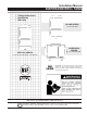
3. Thread one end of 1/4” X 3” brass nipple into bottom of pressure
switch. Thread other end into left 1/4” hole of tank cross. Thread
pressure gauge into right 1/4” hole of tank cross. Cut and
cement as many sections and couplings of PVC pipe needed
to connect the 1” male PVC adapter to pump discharge.
Figure 9. Installed Pressure Switch and Pressure Guage
The complete installation should look like Figure 10 shown below:
Figure 10. Base Mounted Jet Pump With Vertical Tank
Figure 11. Jet Pump Installations
NOTE: NO PRESSURE RELIEF VALVE SHOWN (but is required) ON JET PUMP WITH IN-LINE DRAWING AND JET PUMP MOUNTED ON VERTICAL TANK DRAWING.
SETTING THE TANK PRESSURE
The tank pressure must be set 2 PSI lower than the pump cut-on
pressure. Check tank pressure with a standard air gauge at the
top of the tank as needed.
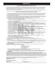
OTHER TANK INSTALLATIONS
Where space is a critical factor, the in-line tank may be used or the
pump may be mounted on either the horizontal or vertical tanks.
Various installations are shown. Also, to increase tank capacity
up to even industrial levels, multiple tanks may be installed on the
same line. See Figure 12. Consult your local pump professional
for your particular installation.
Figure 12. Multi-Tank Installation