
Installation Guide


5
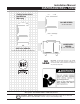
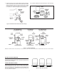
Table 1. Rough-In Dimensions
Capacidad
en galones
Disminución en galones
Dimensiones en centímetros
Conexión de
descarga
Peso en kilos
20 a 40 PSI 30 a 50 PSI 40 a 60 PSI A B C D E
(In-Line)
2 0.7 0.6 --- 10-3/16 --- 8-1/4 --- 3/4 NPTM 5.0
5 1.6 1.4 --- 14-3/4 --- 11 --- 3/4 NPTM 9.0
7 2.5 2.1 --- 21-1/16 --- 11 --- 3/4 NPTM 14.0
(Free-Standing)
14 5.2 4.3 3.7 24-3/4 2-1/4 15-3/8 --- 1” NPTF 25.5
20 7.4 6.2 5.4 32-3/4 2-1/4 15-3/8 --- 1” NPTF 30.0
32 11.5 9.6 8.4 45-1/2 2-1/4 15-3/8 --- 1” NPTF 40.0
36 13.3 11.1 9.7 32-3/8 2-1/4 20 --- 1” NPTF 45.0
52 19.2 16.1 14 38-5/8 2-1/4 23-3/8 --- 1-1/4” NPTF 77.0
65 23.9 20 17.5 46.6 2-1/4 23-3/8 --- 1-1/4” NPTF 87.0
86 31.8 26.7 23.2 59 2-1/4 23-3/8 --- 1-1/4” NPTF 105.0
96 35.5 29.8 25.9 63-3/8 2-1/4 23-3/8 --- 1-1/4” NPTF 111.0
119 44 37 32 61-1/4 2-1/2 26 --- 1-1/4” NPTF 165.0
(Horizontal)
7 2.5 2.1 --- 12-7/8 21-1/8 11 12-1/2 3/4 NPTM 16.0
14 5.2 4.3 3.7 17-3/8 21-3/4 15-3/8 12-1/2 1” NPTM 25.5
20 7.4 6.2 5.4 17-3/8 27-1/8 15-3/8 12-1/2 1” NPTM 30.0
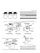
DIAPHRAGM TANK INSTALLATION
PIPING
PVC pipe is shown in the illustrations, but copper or galvanized
steel pipe may be used if desired. All piping must be clean and
free of all foreign matter. ALL JOINTS AND CONNECTIONS IN
THE SYSTEM MUST BE AIRTIGHT. A pin-hole leak will prevent
proper operation of system (this is the most common problem).
Use thread compound on all threads unless specied otherwise.
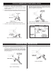
DRAINING FOR SERVICING OR FOR WINTER
The system should be drained before it is disconnected for
servicing, or if it is inoperative for an extended period of time, or
if it is in danger of freezing. To Drain:
• Follow the instructions in your pump installation manual
to drain the pump.
• Open tank drain cock to drain tank.
• Drain all piping to a point 3 feet below ground level.
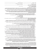
GENERAL MATERIALS*
All diaphragm tanks are recommended for clear water
applications. Vertical tanks are the most commonly used tanks.
However, horizontal tanks and in-line tanks may be used where
space is more critical. See Tank Specications for tank capacity.
• One can PVC cement (read instructions carefully)
• One can thread compound (read instructions carefully)
• One gate valve
• One 1/2” relief valve
• Enough rigid PVC pipe and couplings to reach from pump
to pressure tank to service line.
• One male PVC adapter
• One tank cross
• Two 3/8” plugs
• One 1/2” boiler drain
• One 1/2” street tee
TOOLS NEEDED FOR ALL PUMP INSTALLATIONS
Pipe wrench, crescent wrench, 24-tooth hacksaw, round le or
knife.
REMINDER: All joints and connections must be airtight. A
single pin-hole leak will prevent the proper operation of the
system. Use thread compound on all threaded connections
unless specied otherwise.
* list is for 1” piping installation, if you are installing 1-1/4” pipe
change sizes accordingly.