
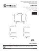
Use and Care Guide


4
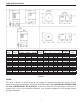
This pump tank is designed and intended for cold (ambient temperature) water storage at a maximum
pressure of 100 PSIG, any use other than with cold water, or at a sustained or instantaneous pressure
inexcessof100PSIGisUNSAFE.Apressurereliefvalveofadequatesizemustbeincorporatedin
the system. The relief valve must be selected to pass the full capacity of the pump when the pressure
in this tank is 100 PSIG or more. Consult pump manufacturer for pump capacity at relief pressure.
The manufacturer of this tank does not accept any liability or other responsibility for personal injury or
property damage resulting from improper use, installation or operation of this tank, or of the system of
which it is a part.
WARNING: Failure to follow these instructions can cause tank to explode and result in DEATH,
SERIOUS BODILY INJURY OR PROPERTY DAMAGE
.
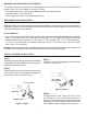
Install a 100 P.S.I. or less pressure relief valve directly into a fitting of the plumbing. Position the valve
downward and provide tubing so that any discharge will exit only within 6 inches above, or at any
distance below the structural floor. Be certain that no contact is made with any live electrical part. The
dischargeopeningmustnotbeblockedorreducedinsizeunderanycircumstances.Excessivelength,
over 15 feet, or in use of more than two elbows can cause restriction and reduce the discharge capacity
of the valve.
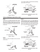
No valve or other obstruction is to be placed between the relief valve and the tank. Do not connect tubing
directlytodischargedrainunlessa6in.airgapisprovided.Topreventbodilyinjuryorhazardtolife,the
valvemustbeabletodischargelargequantitiesofwatershouldcircumstancesdemand.Ifthedischarge
pipe is not connected to a drain or other suitable means, the water flow may cause property damage.
The Discharge Pipe:
•Mustnotbesmallerinsizethantheoutletpipesizeofthevalve,orhaveanyreducingcouplingsor
other restrictions.
•Mustnotbepluggedorblocked.
•Mustbe installed so asto allow complete drainage ofboth the pressure relief valveand the
discharge pipe.
•Mustnothaveanyvalvebetweenthereliefvalveandtank.
WARNING:
The complete pump, tank pressure relief valve, pressure switch and piping system
MUSTbeprotectedagainstbelowfreezingtemperature.Failuretodosocouldcausetank
to explode
and result in DEATH, SERIOUS BODILY INJURY OR PROPERTY DAMAGE.
The pump tanks are designed for operation on water systems with working pressure not to exceed
100PSI.Pressureexceedingthiscouldbecomehazardous,andwillvoidanyandallwarranties,either
written or implied.
IMPORTANT
It will be necessary to expel all air from piping after new installations, repriming and after pumps have
been disassembled for repair. To purge the air, first open a faucet the greatest distance from the pump.
With the pump being allowed to run, wait until a steady stream of water is coming from the faucet. At
this time, close the faucet for several short intervals.
If, after this, air is still in the lines, check on the suction side of the pump for piping leaks.
When standard type tanks are replaced with this tank, all air charging devices, bleeder orifices and air
volume controls must be removed.
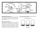
The pump tank has been shipped with a factory precharge as indicated on the tank label. If your pump
start-up pressure is different from the factory precharge, adjust the tank pressure with the empty tank to
your pump start-up pressure. This can be accomplished by simply bleeding air from valve in the top of
the tank with an accurate pressure gauge. Using the same standard air charging valve in the top tank,
a tire pump can be used to raise the tank pressure. Raise the pressure slowly, checking it periodically
with an accurate tire pressure gauge, until the desired pressure is reached.