
Installation Guide
With power disconnected to your electrical box, remove the old fixture. If your old fixture is attached to
an electrical box having more than two (2) wire leads, it is recommended you use tape and markings
to keep track of which wires were attached to each other.
PREPARATION
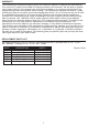
ASSEMBLY INSTRUCTIONS
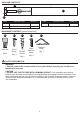
Before beginning assembly of product, make sure all parts are present. Compare parts with
package contents list and diagram above. If any part is missing or damaged, do not attempt to
assemble the product. Contact customer service for replacement parts.
Estimated Assembly Time: 45 minutes
Tools Required for Assembly (not included): Phillips head screwdriver, flathead screwdriver, safety
glasses, electrical tape, pliers, wire cutters, wire strippers, step ladder, hammer.
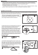
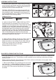
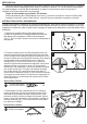
2. Position the fixture (A) on the electrical box, then mark the
location of the narrow ends of the keyhole slots onto the
ceiling. Locate the keyhole slots on the ends of the
fixture (A), and mark the placement of the narrow end on the
mounting surface (Fig. 2). Drill a 1/16 in. pilot hole into the
marked screw locations. You can also use an awl or nail to
dimple the screw holes. If the fixture is being mounted to
drywall, the drywall anchors (CC) will need to be installed. To
install the drywall anchors (CC), drill two 3/16-in. pilot holes
into the drywall. Insert the drywall anchors (CC) into the proper
holes and screw them into place so they are flush with the
surface of the drywall.
Hardware Used
Drywall
Anchor
CC
x 2
1.
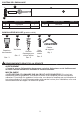
Remove the appropriate knockouts on the back of the
fixture pan that correspond to the positions of the
mounting ears on the electrical box (Fig. 1). This can be
done using a flathead screwdriver and pliers.
A
1
2
A
CC
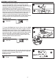
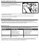
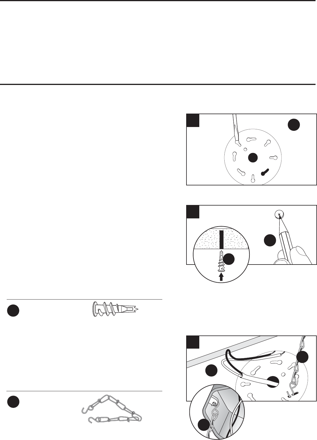
3. Pull the fixture wires through the hole in the center of the
fixture pan (A) to the backside of the fixture. Using the support
chain (NN), connect one end to the back of the fixture pan near
the center in the specially designed slots and hook the other
end to the mounting ears on the electrical box (Fig. 3). This will
allow for a hands free support for wiring.
Hardware Used
x 1
Support Chain
NN
3
A
NN
NN
3