
Installation Guide


8
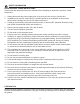
EXISTING CONSTRUCTION ASSEMBLY INSTRUCTIONS
INSTALLATION FROM BELOW (NO ATTIC ACCESS)
1
Wood support screwed in from underneath.
Screw is far enough away from the edge of
ceiling board to prevent crumbling.
Wood support
1. Attach a piece of wood (not supplied; suggested size is
1 in. x 3 in. x 14 in.) from below through the ceiling board
using screws (not included). Position the screws far
enough away from the edge of the ceiling board that it
does not crumble and give way. Put screws in both ends
of wood beyond the 10.25 in. hole. Keep screws in range
of grille.
NOTE: No suspension brackets are needed for this
method of installation.
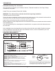
2. Place the duct connector (F) through the ceiling cut out.
Connect a 4 in. circular duct (2.1) (not supplied) and vent
to the outside. Secure it with duct tape (not supplied) or
clamp (not supplied) to make connection secure and air
tight.
Attach the duct connector (F) to the ceiling with one long
wood screw (AA).
2
2.1
AA
F
3.5 in
.
Hardware Used
AA
Long wood screw
x 1
3. Remove fan junction box cover (3.1). Using quick
connector, connect house wires to fan wires (3.2) as
shown in wiring diagram on page 5. Wire connections as
follows: black to live switch wire, white to neutral, green to
ground. Reattach fan junction box cover (3.3).
3
House
wires
Product
wires
3.1
3.2
3.3
r
Quick
connector
4. Insert fan housing (A) into ceiling cut out, making sure to
align the duct connector with the fan housing (A).
4
A
5. Secure the fan housing (A) from below using 2 long wood
screws (AA) through the ange into the wood support
and 2 long wood screws (AA) through the ange into
the joist.
Turn on the power source. Check fan for any abnormal
sound or vibration.
5
A
AA
Hardware Used
AA
Long wood screw
x 4