
Installation Guide

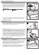
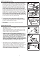

2. Once you have determined the position the fixture will be
mounted, mark the corresponding knock-out closest to your
supply wire feed and remove it. CAREFULLY REMOVE THE
KNOCK-OUT BY HAMMERING A FLATHEAD
SCREWDRIVER OR PUNCH UNTIL THE SURFACE
BREAKS. If the knock-out did not break free, use pliers and
bend it back and fourth until it snaps off.
3. Attach the supplied strain relief (CC) by inserting the threaded
end (from outside the fixture) through the knock-out. Secure the
strain relief (CC) to the fixture’s chassis by tightening the
fastener (from inside the fixture). NOTE: Remember to have the
strain relief screws oriented in a manner that allows you to
tighten/loosen the clamp screws after the fixture had been
attached to the mounting surface.
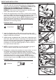
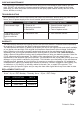
DIRECT WIRE INSTALLATION
4. Insert the flexible whip or NM cable through the strain relief
(CC) and tighten the clamp until it is secure. Allow enough wire
length to make the connection.
5.
Inside the wire compartment are 2 lead wires, a black wire and
white wire, both with crimp-on connectors over the ends of the
wires, as well as a green ground wire. These are the only wires
that will be connected to the supply wires. NOTE: It may be
necessary to cut the ties holding groups of wires in order to
free up the fixures’ lead wires.
6. NOTE: It may be necessary to cut the ties holding groups of
wires in order to free up the fixures’ lead wires.
7.
Using
pliers, uncrimp the connectors to remove them, or use a
wire cutter to cut each lead directly below the crimp-on
connector. When cutting, make sure there is enough wire to
complete the connection. After removing the wire nut, carefully
strip away about 3/8 in. of the insulation. NOTE: Do not
remove the crimp-on connectors and try to use them again.
Use the screw-on wire nuts (BB) included in the hardware kit.
Hardware Used
Strain Relief x 1
CC
5
A
CC
2
A
A
CC
3
6
7
4
5
Hardware Used
Wire Nut x 3
BB