
Operating Instructions


5. Align and install the magnier onto the Picatinny rail with
the position selected in Step 3. Follow instructions below
to adjust for optimal tension
for quick detach, locking and
unlocking.
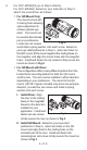
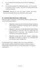
a. Turn the Cam Lever toward its
unlocked position as shown in
Fig 4. Place the QD mount on
the Picatinny rail at the desired
position. Make sure to seat the
cross bolt into a selected slot.
b. Turn the Cam Lever toward the locking position to begin
locking the QD mount on the rail, but do not complete the
locking motion, leaving some travel distance to allow for
adjustment.
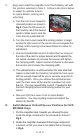
c. Use the included Allen wrench to adjust the hex screw at
the side of the cam for proper tension and t against the
rail. Adjust clockwise to increase the tension and tighten
the clamping width. Adjust counter-clockwise to decrease
the tension and increase the clamping width.
d. The optimal tension is achieved when the side plate rst
makes contact with the Picatinny rail while the Cam Lever
still has enough travel left for you to securely snap into its
locking position. Once you achieve the optimal tension,
push the Cam Lever all the way for a positive lock onto
the rail. You may repeat Step c and d if needed to nd
the best clamping tension and locking position for your
mount.
e. Now your QD Cam Lever is set for quick detach
operations. You may regularly inspect and adjust the
tension for best t.
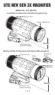
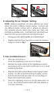
D. Switch Between Vertical/Flip-over Positions (for SCP-
MF3WQS Only):
I. Pull the magnier back towards you allowing the pins
inside the hinge component to be unlocked as shown in
Fig 5.
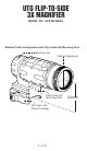
II. Rotate the magnier clockwise till the hinge component
is locked, so that your view is not obstructed as showing
in Fig 6.
6 of 8
Fig 4.