
User Manual
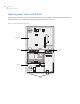
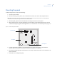
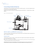
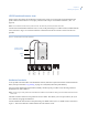
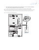

Table Of Contents
- Preface
- Chapter 1 Introduction
- Chapter 2 Planning
- Chapter 3 Installing the system
- UL listed installations
- SIA system requirements
- Central station reporting
- UL Canada listed installations
- California state fire marshall listed installations
- Opening panel cover and chassis
- Mounting the panel
- Connecting hardwired devices
- Wiring a phone line to the panel
- Wiring the power transformer
- Installing X10 modules
- Chapter 4 Programming
- Programming overview
- Menu navigation
- System programming
- Resetting memory to the factory defaults
- Chapter 5 Testing
- Chapter 6 Troubleshooting and support
- Appendix A Specifications and tables
- Index

Chapter 3
Installing the system
27
Wiring a phone line to the panel
You can connect a phone line to the panel for systems monitored by a central monitoring station or systems that
notify users by a voice event notification.
DSL (digital subscriber line) allows the use of multiple devices on a single phone line simultaneously. For
DSL environments, connect the panel line-in jack to an available phone jack on the premises. You might also
need an inline filter to ensure panel reporting is successful.
Note: Avoid connecting the panel to a standard phone (voice) line in this manner. Other devices in use at the same time the
panel is using the line can prevent reports from going through.
Full line seizure
Full line seizure allows the panel to take over (seize) the phone line, even if another device on the line is in use.
This method requires that the panel be wired before all other phones, answering machines, computers, or other
devices on the phone line. You may need to verify line seizure for UL installations.
Use the RJ31X (CA-38A) jack (Figure 8 on page 28) when wiring for full line seizure. This lets the user
quickly and easily disconnect the panel from the phone line in case the panel disables the phone line due to a
malfunction.
Full line seizure wiring with an RJ31X
1. Run a four-conductor cable A from the premises Telco block D to the RJ31X B.
2. Connect the four-conductor cable
A wires to the RJ31X B.
3. Disconnect the green and red premises phone jack wires from the Telco block
D and splice them C to
the four-conductor cable
A black and white (or yellow) wires. Use weatherproof wire connectors for
these splices.
4. Connect the four-conductor cable
A green and red wires to the Telco block D TIP (+) and red to RING
(–) posts.
5. Connect the phone cord
E included with the panel to the RJ31X B and the panel LINE jack.