
User Manual
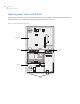
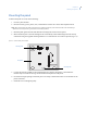
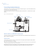
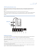
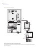
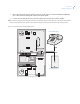

Table Of Contents
- Preface
- Chapter 1 Introduction
- Chapter 2 Planning
- Chapter 3 Installing the system
- UL listed installations
- SIA system requirements
- Central station reporting
- UL Canada listed installations
- California state fire marshall listed installations
- Opening panel cover and chassis
- Mounting the panel
- Connecting hardwired devices
- Wiring a phone line to the panel
- Wiring the power transformer
- Installing X10 modules
- Chapter 4 Programming
- Programming overview
- Menu navigation
- System programming
- Resetting memory to the factory defaults
- Chapter 5 Testing
- Chapter 6 Troubleshooting and support
- Appendix A Specifications and tables
- Index

Simon XT
Installation Manual
24
Connecting hardwired devices
The panel has seven screw terminals and two telephone connections (Figure 5). The screw terminals connect
AC power, sirens, and/or hardwired detectors.
Program sensors and devices before you install them. Follow the instructions in to add the sensors to panel
memory.
Figure 5. Simon XT terminal connections
HW1 I/O, HW2 in, and HW1&2 DC out terminals
The HW1 I/O terminal is dual purpose and can be used for either siren or hardwired contact connections. The
HW2 in terminal is an input only.
Interior sirens
From the factory, the HW1 I/O input is set up for interior siren operation (status and alarm sounds). HW1&2
DC out provides the positive (+) voltage.
Note: The total current available from the HW1&2 DC out terminal is 250 mA at up to 120°F (49°C). A 24-hour battery standby for
UL Requirements will be met with a maximum load of 250 mA.
With Hardwired Siren Supervision turned on, sirens connected to HW1 I/O are supervised and require a
4.7 kohm resistor in the circuit. If this terminal is not used, turn Hardwired Siren Supervision off.
9 VAC in
Battery – neg
Battery compartment
Battery + pos
HW1&2 DC out
HW2 in
HW1 I/O
RJ11 connector (PHONE)
RJ45 connector (LINE)
Tamper switch