
User Manual
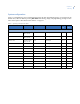
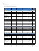
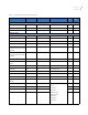
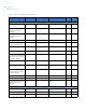
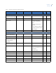
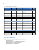
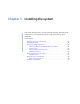
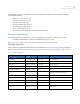
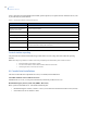
Table Of Contents
- Preface
- Chapter 1 Introduction
- Chapter 2 Planning
- Chapter 3 Installing the system
- UL listed installations
- SIA system requirements
- Central station reporting
- UL Canada listed installations
- California state fire marshall listed installations
- Opening panel cover and chassis
- Mounting the panel
- Connecting hardwired devices
- Wiring a phone line to the panel
- Wiring the power transformer
- Installing X10 modules
- Chapter 4 Programming
- Programming overview
- Menu navigation
- System programming
- Resetting memory to the factory defaults
- Chapter 5 Testing
- Chapter 6 Troubleshooting and support
- Appendix A Specifications and tables
- Index

Simon XT
Installation Manual
16
Emergency planning
Use these guidelines when drawing an emergency floor plan for the homeowner:
• Show all building levels.
• Show exits from each room. (We recommend two exits per room.)
• Show the locations of all security system components.
• Show the locations of any fire extinguishers.
Audio verify menu
Audio mode
b
Off Off Off - Audio mode disabled
1 - Instant mode
2 - Callback mode
D, I
Fire shutdown
b
Off Off On/Off D, I
Panic talk
b
Off Off On/Off D, I
Vox receiver gain
b
6 6 1 to 32 D, I
Vox mic gain
b
24 24 1 to 64 D, I
Vox mic gain range
b
64 64 1 to 64 D, I
Manual mic gain
b
64 64 1 to 64 D, I
Light control menu
Set entry lights
b
Off Off On/Off for each unit number
from 1 to 8
D, I, M
Sensor light
b
Off Off 1 to 8, Off D, I, M
Light schedule
b
None None HH:MMx for start and stop
times, None
D, I, M
Housecode
b
AA A to O D, I, M
Lock interval
b
None None HH:MMx for start and stop
times, None
D, I, M
System test menu
Sensor test D, I, M
Communication test D, I, M
System download
b
D, I, M
a. This column tells what type of access code is allowed to make changes: D = dealer code, I = installer code, M = master code.
b. Not investigated for use by UL.
Table 6. System programming menu options (continued)
Function Default Delete Range Access
code
a
Installer
settings