
Installation Manual
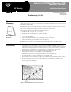
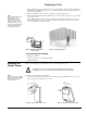
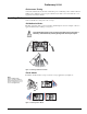
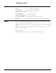
Table Of Contents
- Sentrol AP750W Wireless PIR Motion Sensor
- Product Summary
- Installation
- Mounting the Motion Sensor
- Setting the Sensor Coverage Area and Sensitivity
- Walk Testing
- Installing Masks
- Programming
- 1. Put the panel into program mode.
- 2. Advance to the learn sensors menu.
- 3. Enter the appropriate sensor group and desired sensor number.
- 4. When the panel prompts you to trip the sensor, activate the sensor tamper switch by removing the sensor cover.
- 5. Reattach the sensor cover.
- 6. Exit from program mode.
- Final Testing
- 1. After the sensor has been mounted, remove the sensor cover to trip the tamper switch and acti vate the walk test mode.
- 2. Replace the sensor cover.
- 3. Place the control panel in test mode.
- 4. Move across the detection pattern until the sensor LED turns on, then STOP your motion.
- 5. Listen for the appropriate system response. If the system does not respond, proceed to the “Troubleshooting” section.
- Maintenance
- Replacing Batteries
- Note Avoid touching the mirror. Fingerprints may affect detection coverage
- 4. Carefully remove the PIR (lower) circuit board by pressing outward on either side tab, then pull up on the circuit board (see Figure 12).
- 5. Remove the PIR circuit board battery (located on opposite side of components) and install a new one, observing polarity (marked on the circuit board).
- 6. Re-install the PIR circuit board into the sensor plastic.
- 7. Re-install the transmitter circuit board onto the PIR circuit board.
- 8. Install a new battery in the transmitter circuit board, observing polarity (marked in battery bucket).
- Lithium Battery Disposal
- Troubleshooting
- Specifications
- Notices
- These devices comply with part 15 of the FCC rules. Operation is subject to the following two conditions:
- 1. These devices may not cause harmful interference.
- 2. These devices must accept any interference received, including interference that may cause undesired operation.
- Changes or modifications not expressly approved by Interactive Technologies, Inc. can void the users’ authority to operate the equipment.
- FCC ID: B4Z-844-PIR
- U.S. Patent Nos: 4,855,713, 4,864,636, 5,761,206, 5,805,063, 5,872,512, and 5,942,981
- Preliminary 9/1/04

)
1
,QVWDOODWLRQ,QVWUXFWLRQV
ZZZJHVHFXULW\FRP
*(6HFXULW\
Product
Summary
A motion sensor (passive-infrared or PIR) detects movement by sensing the infrared energy
emitted from a body as it moves across its field of view. When this motion is detected, the sensor
transmits an alarm signal.
Install motion sensors to protect areas where door/window sensors are impractical or not needed.
For example, use a motion sensor to protect large areas or open floor plans. Motion sensors can
also provide backup protection in areas where door/window sensors exist.
This wireless motion sensor includes the following features:
• Field-selectable coverage area; 33 or 50 feet
• Field-selectable sensitivity modes; 2-pulse or 4-pulse
• 135-second transmitter lockout time after an alarm that helps extend battery life
• Cover-activated tamper
• Supervisory signal transmitted every 64 minutes to the control panel
• Sensor low battery reports (trouble) to the control panel
Included with the sensor is a thin cardboard undercrawl mask and snap-in plastic masks
(installed at the factory). Self-adhesive masking strips are also included.
Installation • If possible, locate sensors within 100 feet of the panel. While a transmitter may have an
open-air range of 500 feet or more, the installation site can have a significant effect on trans-
mitter range. Changing the sensor location may help overcome adverse wireless conditions.
• Mount the sensor permanently on a flat wall or in a corner. Do not set it on a shelf.
• For installations without pets, the required mounting height is 7 1/2 feet.
• Mount the motion sensor on an insulated, outside wall facing in.
• Mount the motion sensor on a rigid surface which is free from vibrations.
• Position the sensor so it faces a solid reference point, like a wall.
• Do not aim the sensor at windows, fireplaces, air conditioners, heaters/heating vents, or place
it in direct sunlight.
• Position the sensor to protect an area where intruders are most likely to walk across the
detection pattern (see Figure 1).
Figure 1. Overhead (Bird’s Eye View) Detection Path
Person walking across detection path.
'RFXPHQW1XPEHU;;5HY
6HSWHPEHU
35(/,0,1$5<
Preliminary 9/1/04
6HQWURO$3::LUHOHVV3,5
0RWLRQ6HQVRU
Model No.
60-991-900