
User's Manual
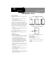
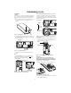
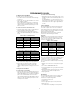
Table Of Contents
- Product Summary
- Installation Guidelines
- Installation
- 1. Insert a slotted screwdriver into the slot at the top end of the unit and remove the cover by lifting it up (see Figure 2).
- 2. Using the flathead mounting screws, secure the base to the mounting surface either vertically or horizontally as required (see Figure 3).
- 3. Position the shock element and press it firmly into its socket.
- 4. If using the reed switch, use the two remaining screws to mount the magnet so its arrow is aligned with the arrow on the sensor case (see Figure 7).
- 5. Install the tamper switch as shown (see Figure 7).
- 6. Install the 4.7 k Ohm EOL resistor across the terminals of the external switch block.
- Setting the Detection Mode
- 1. Hold in the tamper spring. Continue to hold in while mov ing the DIP switches to their desired settings.
- 2. Set the DIP switches to the desired pulse count (see Table 1). The LED will start blinking once a DIP switch is moved.
- 3. Set the DIP Switches to the desired Gross Attack sensi tivity (See Table 2).
- 4. Release the tamper spring. The LED will flash quickly 3 times to indicate the settings have been programmed.
- 5. Repeat steps 1-4 each time you make a sensitivity change. It may then be necessary to reset the DIP switches to their proper device settings (See Sensor Set tings).
- Testing the Detection Modes
- Sensor Settings
- System Programming
- RF Testing
- Battery Replacement
- Specifications

4
PRELIMINARY 10/1/03
Battery Replacement
When the system indicates that the sensor has a low bat-
tery, remove the old battery and install a new battery (Dura-
cell DL123A or a Sanyo CR123A) into the battery holder,
observing proper polarity.
Caution!
Replace only with a Duracell DL123A battery or a Sanyo
CR123A battery. Observe polarity when installing a new
battery. Installing the battery backwards may cause damage
to the sensor.
Dispose of used batteries according to the manufacturer’s
instructions and/or local government authorities.
Specifications
Model No.: 60-975-95R and 60-975-11-95R
RF Frequency: 319.5 MHz
Compatibility: All GE Interlogix 319.5 MHz Control Panels and
Receivers
Battery Type: 3.0 VDC Lithium
Recommended Battery: GE CR123A
Typical Standby Current (µA): 10
Estimated Battery Life: 5 years (one battery); 10 years (two
batteries)
Typical RF Power Output (mW): 10
Operating Temperature Range (C°): 0 to 49
Storage Temperature Range (C°): -34 to 60
Relative Humidity: 0 - 90% non-condensing
Dimensions (mm): 45 x 115 x 31 (L x W x D)
Weight: 88
6HFRQG6WUHHW1RUWK
1RUWK6DLQW3DXO01
7HFKQLFDO6XSSRUW
)
*(,QWHUORJL[
*(,QWHUORJL[6LPRQLVDUHJLVWHUHGWUDGHPDUNRI*(,QWHUORJL[
$OORWKHUWUDGHPDUNVDUHSURSHUWLHVRIWKHLURZQHUV
$OOULJKWVUHVHUYHG