
User's Manual
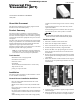
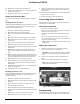
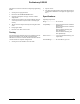
Table Of Contents
- About this Document
- Product Summary
- Installation
- General Sensor Installation Guidelines
- Install on a Wall
- 1. Determine a suitable location for the UFT.
- 2. Mark where the magnet will be installed.
- 3. Drill a 3/4” diameter hole 3/4” deep into the wall.
- 4. Push the magnet into the hole, magnet side first.
- 5. Remove the UFT cover by squeezing the cover ends firmly to release the tab on the cover from t...
- 6. Remove the circuit board from the UFT base by pulling back the plastic tab and lifting the bat...
- 7. Mark where the UFT will be installed over the magnet. See Figure 1 for acceptable magnet locat...
- 8. Verify the UFT reed switch is properly aligned with the installed magnet.
- 9. Mount the UFT base with screws or brads. Use spacers to compensate for metal surfaces or heigh...
- 10. Reattach the circuit board to the UFT base
- 11. Attach the External Switch (See “Connecting External Switch” in this manual)
- 12. Reattach the UFT cover to the UFT base.
- Install in an Electrical Box
- Mounting the box on a wall
- 1. Determine a suitable location for the UFT.
- 2. Mark where the magnet will be installed.
- 3. Drill a 3/4” diameter hole 3/4” deep into the stud or wall.
- 4. Mark where the box will be installed over the magnet.
- 5. Mark the box at the location where the magnet will enter the box.
- 6. Drill a 13/16” hole in the box at the magnet location.
- 7. Mark where the UFT will be installed on the box.
- 8. Verify the UFT reed switch is properly aligned with the magnet hole.
- 9. Mount the box using screws or brads making sure to align the hole in the box with the hole in ...
- 10. Push the magnet, magnet side first, through the hole in the box and into the hole in the stud...
- 11. Mount the UFT in the box using velcro strips.
- 12. Remove the UFT cover by squeezing the cover ends firmly to release the tab on the cover from ...
- 13. Attach the External Switch (See “Connecting External Switch” in this manual)
- 14. Reattach the UFT cover to the UFT base.
- Mounting the box in a wall
- 1. Determine a suitable location for the UFT.
- 2. Mark the box at the location where the magnet will be installed.
- 3. Drill a 3/4” hole in the box at the magnet location.
- 4. Insert the magnet into the hole.
- 5. Mark where the UFT will be installed on the box
- 6. Verify the UFT reed switch is properly aligned with the magnet.
- 7. Mount the box in the wall using screws or brads.
- 8. Mount the UFT in the box using velcro strips.
- 9. Remove the UFT cover by squeezing the cover ends firmly to release the tab on the cover from t...
- 10. Attach the External Switch (See “Connecting External Switch” in this manual)
- 11. Reattach the UFT cover to the UFT base.
- Mounting the box on a wall
- Connecting External Switch
- Programming
- 1. Set the panel to program mode.
- 2. Proceed to the LEARN SENSORS menu.
- 3. Select the appropriate zone type and zone number assignments.
- 4. Set the external switch in the alarm condition (open for a normally closed circuit, closed for...
- 5. Trip the sensors tamper switch by removing the sensor cover.
- 6. Exit program mode.
- 7. Place the cover back on the sensor.
- Testing
- Specifications
- FCC Notice

4
Preliminary 1/22/02
FCC Notice
FCC Part 15 Information to the User
Changes or modifications not expressly approved by Interlogix, Inc. can
void the user’s authority to operate the equipment.
FCC Part 15 Class A
This equipment has been tested and found to comply with the limits for
a class A digital device, pursuant to part 15 of the FCC rules. These
limits are designed to provide reasonable protection against harmful
interference when the equipment is operated in a commercial environ-
ment.
This equipment generates, uses, and can radiate radio frequency energy
and, if not installed and used in accordance with the instruction manual,
may cause harmful interference to radio communications. Operation of
this equipment in a residential area is likely to cause harmful interfer-
ence in which case users will be required to correct the interference at
their own expense.
FCC Part 15 Class B
This equipment has been tested and found to comply with the limits for
a Class B digital device, pursuant to part 15 of the FCC Rules. These
limits are designed to provide reasonable protection against interference
in a residential installation.
This equipment generates, uses, and can radiate radio frequency energy
and, if not installed and used in accordance with the instructions, may
cause harmful interference to radio communications. However, there is
no guarantee that interference will not occur in a particular installation.
If this equipment does cause harmful interference to radio or television
reception, which can be determined by turning the equipment off and
on, the user is encouraged to try to correct the interference by one or
more of the following measures:
❑ Reorient or relocate the receiving antenna.
❑ Increase the separation between the equipment and receiver.
❑ Connect the affected equipment and the panel receiver to separate
outlets, on different branch circuits.
❑ Consult the dealer or an experienced radio/TV technician for help.
FCC ID: B4Z-808-UFT
2266 Second Street North | North Saint Paul Mn | 55109 | 800-777-2624 | www.interlogixinc.com
©2001 Interlogix,™ Inc. Interlogix is a trademark of Interlogix, Inc. ITI, Advent, and SuperBus are registered trademarks of Interlogix, Inc.