
Owner's Manual


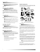
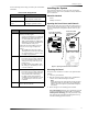
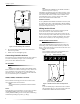
Table Of Contents
- About This Manual
- Special Installation Requirements
- UL Listed Installations
- Basic System
- Household Burglary Alarm System Unit (UL 1023)
- Household Fire Warning System (UL 985)
- UL 1023 & 985 24-Hour Backup
- UL 1635 Digital Alarm Communicator System
- Central Station Reporting
- UL Canada Listed Installations
- Canadian Standards CSA Certified Accessories
- Residential Burglary Alarm System Unit (ORD-C1023-1974)
- Residential Fire Warning System Control Unit (ULC-S545-M89)
- California State Fire Marshall Listed Installations
- Special Installation Requirements
- Planning the Installation
- Installing the System
- System Components
- Figure 1. Typical Security System Components
- Control Panel
- User Interface
- Panel Tamper
- System Devices
- Door/Window Sensor (60-670)
- Indoor Motion Sensor (60-639)
- Outdoor Motion Sensor (60-639)
- Freeze Sensor* (60-742)
- Water Sensor* (60-744)
- Smoke Sensor (60-848-95)
- Carbon Monoxide (CO) Alarm* (60-652-95)
- Keychain Touchpad* (60-659)
- Remote Handheld Touchpad (60-671)
- X-10 Modules*
- Interrogator® 200 Audio Verification Module* (60-787)
- System Components
- Planning Sensor Types & Locations
- Recommended Sensor Types
- Device Locations
- X-10 Modules
- House Code and Unit Numbers
- To Fill Out the Home Control Planning Table:
- 1. Set the house code on all modules (except the remote siren) to the same letter.
- 2. Set the Remote Siren house code to the next alphabetical letter. For example, if you chose hou...
- 3. Set the module unit numbers.
- 4. List the location of the lamp or appliance in the Location column of the Home Control Planning...
- 5. Write the location of each Lamp Module on an adhesive note and label the module.
- 6. Decide if the device should be activated by sensors, entry/exit delay, time, or a combination....
- House Code Assignments
- Installing the System
- Materials Needed
- Opening the Panel Cover and Chassis
- Mounting the Panel
- Connecting Hardwire Devices
- Wiring Interior Sirens
- Wiring Exterior Sirens
- Wiring Hardwire Contacts
- Wiring a Phone Line to the Panel
- Full Line Seizure
- Full Line Seizure Wiring with an RJ-31X
- 1. Run a 4-conductor cable from the TELCO block to the RJ-31X (A in Figure 8).
- 2. Connect the 4-conductor cable wires to the RJ-31X (B in Figure 8).
- 3. Disconnect the Green and Red premises phone jack wires from the TELCO block and splice them to...
- 4. Connect the 4-conductor cable Green and Red wires to the TELCO block TIP (+) and Red to RING (...
- 5. Connect the phone cord included with the panel to the RJ-31X and the panel LINE IN jack (E in ...
- Full Line Seizure Wiring with 1 Premises Phone
- No Line Seizure
- Wiring the Power Transformer
- Powering Up the Panel
- Installing the Panel Backup Battery
- Applying AC Power
- Installing X-10 Modules
- Lamp and Appliance Modules
- Universal Module
- 1. Set the unit code dial to a unit number different from all other X-10 modules (between 1 and 8).
- 2. Set the house code for the installation.
- 3. Set the module switches to momentary and relay only.
- 4. Connect the module terminals to the desired device terminals.
- 5. Plug the universal module into a wall outlet.
- Sensor Installation
- Programming
- Entering Program Mode
- Exiting Program Mode
- Reset Memory to the Factory Defaults
- 1. Open the panel cover and enter Utility Access code 1.
- 2. Unplug the transformer and disconnect the battery.
- 3. Simultaneously press and hold Cancel, Clock Set, and Minutes +.
- 4. Restore power to the panel with either the battery or the transformer while pressing these thr...
- 5. Connect the remaining power source to the panel.
- Set the Clock
- Adding (Learning) Sensors
- Device Programming
- Device
- To Program
- 1. Press Add. The panel announces “Select from Main Menu.”
- 2. Press Sensor/Remote. The panel announces “Press button on sensor.”
- 3. Press the sensor program button or release sensor tamper switch. The panel announces “Keychain...
- 4. Press Sensor/Remote repeatedly until you hear the name or item you want to use. An alphabetica...
- 5. Press DONE when you hear the desired name. The panel announces “Use numbered keys to enter sen...
- 6. Enter the 2-digit sensor group. The panel announces the sensor group and the first available s...
- 7. Press DONE. The panel confirms programming by announcing the sensor number, name, and group.
- Deleting Sensors
- Device Programming
- X-10 Module Operation
- 1. Press Add.
- 2. Press Light Control repeatedly until you hear the desired house code letter.
- 3. Press DONE.
- 4. Set the HOUSE dial on each lamp, appliance, and universal module, to the same letter.
- 5. Set the HOUSE dial on powerhorn/remote sirens to the next sequential alphabetical letter.
- 1. Press Add.
- 2. Press Light Control.
- 3. Press Unit # repeatedly until you hear the unit number that matches the one you chose for the ...
- 4. Press Entry/Exit Delay. The panel confirms your programming.
- 1. Press Add.
- 2. Press Light Control.
- 3. Press Unit # repeatedly until you hear the unit number that matches the one you chose for the ...
- 4. Press Sensors until you hear the sensor you want to control the light.
- 5. Press DONE. The panel confirms your programming.
- 1. Press Add.
- 2. Press Light Control.
- 3. Press Unit # until you hear the unit number that matches the one you chose on the module.
- 4. Press Time.
- 5. Press Hours and Minutes to set the beginning of the schedule.
- 6. Press DONE.
- 7. Press Hours and Minutes to set the end of the schedule.
- 8. Press DONE. The panel confirms your programming.
- 1. Press Delete.
- 2. Press Light Control.
- 3. Press Unit # repeatedly until you hear the unit number you want deleted.
- 4. Press Entry/Exit Delay, then press DONE. The panel confirms your programming.
- 1. Press Delete.
- 2. Press Light Control.
- 3. Press Unit # repeatedly until you hear the unit number you want deleted.
- 4. Press Sensors until you hear the one you want deleted.
- 5. Press DONE. The panel confirms your programming.
- 1. Press Delete.
- 2. Press Light Control.
- 3. Press Unit # repeatedly until you hear the unit number you want deleted.
- 4. Press DONE. The panel confirms your programming
- Numbered Options
- Option 01: Panel Piezo Beeps (Default = On)
- Panel Piezo Beeps
- Activity
- Piezo Beep Response
- To turn on Panel Piezo Beeps, press:
- To turn off Panel Piezo Beeps, press:
- Option 02: Panel Voice (Default = On)
- Option 03: Latchkey (Default = Off)
- Option 04: Primary Phone Number (Default = none)
- Option 05: Secondary Phone Number (Default = none)
- Option 06: Downloader Phone Number (Default = none)
- Option 07: Account Number (Default = 00000)
- Option 08: Phone Lock (Default = off)
- Option 09: Downloader Code (Default = 12345)
- Option 10: Entry Delay (Default = 030 sec)
- Option 11: Exit Delay (Default = 060 sec)
- Option 12: Phone Mod 1 (Default = 0)
- Phone Mod 1
- Phone Mod 2
- Setting #
- Content
- Format
- To set Phone Mod 2, press:
- To reset Phone Mod 2 (return to default), press:
- Option 14: DTMF Dialing (Default = on)
- Option 15: No Activity Time-out (Default = off)
- Option 16: Auto Phone Test (Default = off)
- Option 17: Dialer Delay (Default = off)
- Option 18: Alarm Cancel Report (Default = 005 minutes)
- Option 19: RF Timeout (Default = 12 hours)
- Option 20: Manual Phone Test (Default = on)
- Option 21: Opening Reports (Default = off)
- Option 22: Closing Reports (Default = off)
- Option 23: Force Armed Report (Default = off)
- Option 24: AC Power Failure Report (Default = off)
- Option 25: CPU Low Battery Report (Default = on)
- Option 26: Fail to Communicate (Default = on)
- Option 27: Ring/Hang/Ring (Default = 1)
- Ring/Hang/Ring Settings
- Setting
- Control Panel answers after:
- 1. Call the panel location.
- 2. Let the phone ring once, then hang up.
- 3. Wait at least 10 seconds but not more than 40, then call the panel location again. The panel s...
- To turn on Ring/Hang/Ring, press:
- To turn off Ring/Hang/Ring (disable remote access), press:
- Option 28: No Delay from Keychain Touchpad (Default = off)
- Option 29: Panel Piezo Alarms (Default = on)
- Option 30: Panel Panic Alarms (Default = on)
- Option 31: Downloader Enable (Default = on)
- Option 32: 300 Baud (Default = on)
- Option 33: Audio Verification (Default = off)
- Option 34: Fail to Open Report (Default = off)
- Option 35: Fail to Close Report (Default = off)
- Option 36: Sensor Activated Light Lockout Start Time (Default = off)
- Option 37: Sensor Activated Light Lockout Stop Time (Default = off)
- Option 38: Auto Arm (Default = off)
- Option 39: Siren Timeout (Default = 4 min.)
- Option 40: Trouble Beeps (Default = on)
- Option 41: Chime Voice (Default = off)
- Option 42: Speaker Level (Default = 8)
- Option 43: Numeric Pager/Voice Event Notification Phone Number (Default = off)
- Option 44: Numeric Pager/Voice Event Notification Phone Mod 3 (Default = 09)
- Phone Mod 3
- Sensor Alarm Restoral Settings
- Setting
- When Restorals are Reported
- To turn on Sensor Alarm Restoral Report, press:
- To turn off Sensor Alarm Restoral Report, press:
- Option 46: Fire Shutdown - AVM (Default = off)
- Option 47: AVM Mode (Default = off)
- Option 48: Panic Talk - AVM (Default = off)
- Option 49: Arming LEDs Shutdown (Default = off)
- Option 50: RF Jam Detect (Default = off)
- Option 51: 24 Hour Sensor Tamper (Default = off)
- Option 52: Unvacated Premises (Default = on)
- Option 53: Hardwire Siren Supervision (Default = off)
- Option 54: Access Code Length (Default = 4)
- Access Code Length Defaults
- Setting
- Default Code
- To change Access Code Length, press:
- To reset Access Code Length (to default), press:
- Option 55: Status Beep Volume (Default = 07)
- Option 56: Call Waiting (Default = off)
- Option 57: Supervisory/Tamper Report (Default = off)
- Option 58: Remote Touchpad Arming (Default = off)
- Option 59: Exit Extension (Default = on)
- Option 60: Secure Arming (Default = off)
- Option 61: Demo Mode (Default = off)
- Option 62: Supervisory Protest (Default = off)
- Option 63: 24 Hour Time (Default = off)
- Option 64: No Arm on Panel Low Battery (Default = off)
- Option 65: No Usage Report (Default = off)
- Option 66: External Siren Delay (Default = off)
- Option 67: Quick Exit (Default = off)
- Option 68: Swinger Shutdown (Default = on)
- Option 69: SIA Limits (Default = on)*
- SIA Limits
- Affected Option
- SIA Limits (Option 69 on)
- Factory Ranges (Option 69 off)
- To turn on SIA Limits, press:
- To turn off SIA Limits, press:
- Option 70: Not Available
- Option 71: Programming Report (Default = off)
- Option 72: Supervisory Time (Default = 12:00am)
- Option 73: Modem Sensitivity (Default = off)
- Option 74: Silent Panel Police Panic (Default = off)
- Option 75: VOX Mic Gain (Default = 14)
- Option 76: VOX Gain Range (Default = 64)
- Option 77: Manual Mic Gain (Default = 64)
- Option 78: VOX Receiver Gain (Default = 6)
- Option 79: Panel Cover Tamper (Default = off)
- Option 80: Alarm Report Verification (Default = off)
- Programming System Access Codes
- Master Access Code
- Access Codes (1 - 5)
- Panic Code
- 1. Press Add.
- 2. Press Access Code button. Continue pressing this button until you hear the access code to be c...
- 3. Press DONE.
- 4. Enter the new access code by using the numbered keys. The panel announces the new code.
- 1. Press Delete.
- 2. Press Access Code. Continue pressing this button until you hear the access code to be deleted.
- 3. Press DONE. The panel announces the code is deleted.
- Testing the System
- Control Panel
- Sensors
- Improving Sensor/Panel Communication
- Phone Communication
- Off-Site Phone Operation
- Central Station Communication
- To test communication with the central station:
- 1. Call the central station and tell the operator that you will be testing the system.
- 2. Arm the system.
- 3. Test each of the wireless panic buttons and trip at least one sensor of each type (fire, intru...
- 4. When you finish testing the system, call the central station to verify that the alarms were re...
- User Codes for Opening and Closing Reports
- To test communication with the central station:
- Pager Communication
- 2-Way Voice Operation
- Voice Event Notification
- 1. Contact the central monitoring station (if system is monitored) to inform them you are testing...
- 2. At the system site, put the system into an alarm condition.
- 3. At the calling location, pick up the phone after it starts ringing. You should hear the panel ...
- 4. Press Ç and the panel voice identifies the alarm. If there is more than one alarm in progress,...
- 5. After listening to the alarm information, press É to terminate the call.
- X-10 Operation
- Emergency Planning
- Appendix A: Troubleshooting
- Appendix B: System Configuration
- Specifications

FCC Notices
FCC Part 15 Information to the User
Changes or modifications not expressly approved by Interlogix Inc. can void the user’s authority to operate the equipment.
FCC Part 15 Class B
This equipment has been tested and found to comply with the limits for a Class B digital device, pursuant to part 15 of the FCC Rules. These limits are
designed to provide reasonable protection against interference in a residential installation.
This equipment generates, uses, and can radiate radio frequency energy and, if not installed and used in accordance with the instructions, may cause harmful
interference to radio communications. However, there is no guarantee that interference will not occur in a particular installation.
If this equipment does cause harmful interference to radio or television reception, which can be determined by turning the equipment off and on, the user is
encouraged to try to correct the interference by one or more of the following measures:
Reorient or relocate the receiving antenna.
Increase the separation between the equipment and receiver.
Connect the affected equipment and the panel receiver to separate outlets, on different branch circuits.
Consult the dealer or an experienced radio/TV technician for help.
FCC ID: B4Z-787E-SIMON
ACTA Part 68
This equipment complies with Part 68 of the FCC Rules. Located on this equipment is a label that contains, among other information, the FCC registration
number and the ringer equivalence number (REN) for this equipment. If requested, this information must be provided to the telephone company.
FCC Part 68 Registration No.
The REN is used to determine the maximum number of devices that may be connected to your telephone line. Excessive RENs on a telephone line may result
in devices not ringing in response to an incoming call. In most areas, the sum of all device RENs should not exceed five (5.0). To be certain of the number of
devices that may be connected to a line, as determined by the total RENs, contact the local telephone company. For products approved after July 23, 2001, the
REN for this product is part of the product identifier that has the format US:AAAEQ##TXXXX. The digits represented by ## are the REN without a decimal
point (e.g., 03 is a REN of 0.3). For earlier products, the REN is separately shown on the label.
A plug and jack used to connect this equipment to the premises wiring and telephone network must comply with the applicable FCC Part 68 rules and require-
ments as adopted by ACTA. A compliant telephone cord and modular plug is provided with this product. It is designed to be connected to a compliant modu-
lar jack that is also compliant. See the Installation Instructions for details.
Alarm dialing equipment must be able to seize the telephone line and place a call in an emergency situation. It must be able to do this even if other equipment
(telephone, answering system, computer modem, etc.) already has the telephone line in use. To do so, alarm dialing equipment must be connected to a prop-
erly installed RJ31X jack that is electrically in series and ahead of all other equipment attached to the same telephone line. Proper installation is depicted in
the following diagram. If you have any questions concerning these instructions, consult your local telephone company or a qualified installer about installing
an RJ31X jack and alarm dialing equipment for you.
If this equipment causes harm to the telephone network, the telephone company may temporarily disconnect your service. If possible, you will be notified in
advance. When advance notice is not practical, you will be notified as soon as possible. You will also be advised of your right to file a complaint with the
FCC.
The telephone company may make changes in its facilities, equipment, operations, or procedures that could affect the operation of the equipment. You will be
given advance notice in order to maintain uninterrupted service.
If you experience trouble with this equipment, please contact the company that installed the equipment for service and/or repair information. The telephone
company may ask you to disconnect this equipment from the network until the problem has been corrected or you are sure that the equipment is not malfunc-
tioning.
This equipment may not be used on coin service provided by the telephone company. Connection to party lines is subject to state tariffs.
N e t w o r k
S e r v i c e
P r o v i d e r ' s
F a c i l i t i e s
T e l e p h o n e
L i n e
N e t w o r k
D e m a r c a t i o n
P o i n t
T e l e p h o n e
A n s w e r i n g
S y s t e m
F a x M a c h i n e
C o m p u t e r
T e l e p h o n e
T e l e p h o n e
A l a r m D i a l i n g
E q u i p m e n t
R J 3 1 X
J a c k
U n u s e d
R J - 1 1 J a c k
U n u s e d
R J - 1 1 J a c k
C u s t o m e r P r e m i s e s E q u i p m e n t a n d W i r i n g