
User's Manual
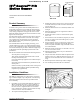
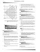
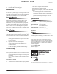
Table Of Contents
- Product Summary
- Installation Guidelines
- 1. If possible, locate sensors within 100 feet of the panel. While a transmitter may have a range...
- 2. The required mounting height is 7 1/2 feet.
- 3. Position the sensor to protect an area where an intruder would be most likely to walk across t...
- 4. Mount the motion sensor on an insulated, outside wall facing in.
- 5. Mount the motion sensor on a rigid surface which is free from vibrations.
- 6. Position the sensor so it faces a solid reference point, like a wall.
- 7. Do not aim the sensor at windows, fireplaces, air conditioners, area heaters, forced air heati...
- 8. Do not mount the sensor near duct work or other large metallic surfaces which may affect the R...
- 9. Mount the sensor permanently on a flat wall or in a corner. Do not set it on a shelf.
- 10. Windows should be closed in any area which has an armed motion sensor.
- 11. The pet must not be allowed to climb on objects such as furniture, boxes, etc. within the fie...
- 12. Room temperature must be kept at 60º F or higher.
- 13. The sensitivity switch must be set to Standard.
- Mounting the Motion Sensor
- To mount the sensor:
- 1. Remove the mounting plate by depressing the button on the top of the sensor body. With the opp...
- 2. Punch out two of the bottom four mounting holes. Use the lower-side holes for corner mounting,...
- 3. If you desire wall-tamper functionality, remove the wall-tamper knockout.
- 4. Mark the location of the required holes on the mounting surface.
- 5. Use wall anchors and screws to secure into place. Attach the sensor to the mounting plate.
- 6. When testing is completed the PIR can be securely attached to its mounting plate by screwing t...
- To mount the sensor:
- Setting the Sensitivity on the Indoor Motion Sensor
- Walk Testing the Motion Sensor
- Environment Testing
- Programming
- Maintenance
- Final Testing
- 1. After the sensor has been mounted, remove it from its mounting plate and activate the tamper s...
- 2. Replace the sensor in its mounting plate.
- 3. Place the control panel in test mode. Move across the detection pattern until the sensor’s LED...
- 4. Listen for the appropriate system response. If the system does not respond, proceed to Trouble...
- Troubleshooting
- Specifications
- Notices
- ITI® Sentrol™ PIR Motion Sensor

3
ITI® Sentrol™ PIR Motion Sensor
Maintenance
Preliminary 4/5/00
2. Exit the panel’s programming mode.
3. Return the PIR to its mounting plate.
Maintenance
At least once a year, the range and coverage should be veri-
fied for proper operation. The end user should be instructed
to put the sensor in walk test mode and walk through the far
end of the coverage pattern to verify proper detection.
Replacing Batteries
When battery replacement is necessary, observe proper
polarity (as shown in the battery compartment) when
installing the new battery, or the sensor may be damaged.
Be sure to note that as you look at the battery compartment,
on the left side the positive side is down and on the right
side the positive end is up. When the battery is replaced,
wait at least 3 minutes after installing the battery before
activating the walk test mode. See Figure 7 for battery loca-
tions.
Final Testing
Final testing should be done to verify radio signal integrity
and confirm control panel programming and response. The
actual transmitter range can be determined by performing a
sensor test as follows:
1. After the sensor has been mounted, remove it from its
mounting plate and activate the tamper switch to start
the walk test mode.
2. Replace the sensor in its mounting plate.
3. Place the control panel in test mode. Move across the
detection pattern until the sensor’s LED turns on.
STOP your motion.
4. Listen for the appropriate system response. If the sys-
tem does not respond, proceed to Troubleshooting.
Troubleshooting
Use the following guidelines if the system does not respond
correctly when the sensor is activated.
❑ Check programming and re-program sensor into panel
if necessary.
❑ Move the sensor to another location and test for correct
response.
To relocate a sensor:
1. Test the sensor a few inches from the original position.
2. Increase the distance from the original position and
retest until an acceptable location is found.
3. Mount the sensor in the new location.
4. If no location is acceptable, test the sensor as described
below:
❑ Test a known good sensor at the same location.
❑ If the system does not respond, avoid mounting a
sensor at that location.
❑ If the replacement sensor functions, return the
problem sensor for repair or replacement.
Specifications
Power source: One 3-volt lithium (CR123A) bat-
tery
Typical battery life: 2-4 years at 68° F
(not verified by U.L.)
Temperature Range: 32° to 120° F (
60° to 120° F (Pet applications)
Dimensions:
Notices
These devices comply with part 15 of the FCC rules. Oper-
ation is subject to the following two conditions:
1. These devices may not cause harmful interference.
2. These devices must accept any interference received,
including interference that may cause undesired operation.
Changes or modifications not expressly approved by Inter-
active Technologies, Inc. can void the users’ authority to
operate the equipment.
FCC ID: B4Z-780A-PIR
Patent No: 4,855,713
651-777-2690
651-779-4890
ITI is a registered trademark of Interactive Technologies, Inc. Sentrol is a
trademark of .......