
User's Manual
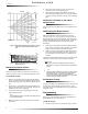
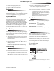
Table Of Contents
- Product Summary
- Installation Guidelines
- 1. If possible, locate sensors within 100 feet of the panel. While a transmitter may have a range...
- 2. The required mounting height is 7 1/2 feet.
- 3. Position the sensor to protect an area where an intruder would be most likely to walk across t...
- 4. Mount the motion sensor on an insulated, outside wall facing in.
- 5. Mount the motion sensor on a rigid surface which is free from vibrations.
- 6. Position the sensor so it faces a solid reference point, like a wall.
- 7. Do not aim the sensor at windows, fireplaces, air conditioners, area heaters, forced air heati...
- 8. Do not mount the sensor near duct work or other large metallic surfaces which may affect the R...
- 9. Mount the sensor permanently on a flat wall or in a corner. Do not set it on a shelf.
- 10. Windows should be closed in any area which has an armed motion sensor.
- 11. The pet must not be allowed to climb on objects such as furniture, boxes, etc. within the fie...
- 12. Room temperature must be kept at 60º F or higher.
- 13. The sensitivity switch must be set to Standard.
- Mounting the Motion Sensor
- To mount the sensor:
- 1. Remove the mounting plate by depressing the button on the top of the sensor body. With the opp...
- 2. Punch out two of the bottom four mounting holes. Use the lower-side holes for corner mounting,...
- 3. If you desire wall-tamper functionality, remove the wall-tamper knockout.
- 4. Mark the location of the required holes on the mounting surface.
- 5. Use wall anchors and screws to secure into place. Attach the sensor to the mounting plate.
- 6. When testing is completed the PIR can be securely attached to its mounting plate by screwing t...
- To mount the sensor:
- Setting the Sensitivity on the Indoor Motion Sensor
- Walk Testing the Motion Sensor
- Environment Testing
- Programming
- Maintenance
- Final Testing
- 1. After the sensor has been mounted, remove it from its mounting plate and activate the tamper s...
- 2. Replace the sensor in its mounting plate.
- 3. Place the control panel in test mode. Move across the detection pattern until the sensor’s LED...
- 4. Listen for the appropriate system response. If the system does not respond, proceed to Trouble...
- Troubleshooting
- Specifications
- Notices
- ITI® Sentrol™ PIR Motion Sensor

2
ITI® Sentrol™ PIR Motion Sensor
Programming
Preliminary 4/5/00
Figure 2.This graph shows the top view of the lens cov-
erage area, for the indoor motion sensor’s
lens.
Figure 3.Side View (Motion Sensor) at a mounting
height of 7.5 feet.
Mounting the Motion Sensor
This sensor must be incline-mounted on a wall surface or
incline mounted in a corner at a mounting height of 7.5 feet.
To mount the sensor:
1. Remove the mounting plate by depressing the button
on the top of the sensor body. With the opposite hand
pull the mounting plate away from the body of the sen-
sor.
2. Punch out two of the bottom four mounting holes. Use
the lower-side holes for corner mounting, or the lower-
middle holes for surface mounting.
3. If you desire wall-tamper functionality, remove the
wall-tamper knockout.
Note
The wall-tamper switch cannot be used when the sen-
sor is corner mounted.
4. Mark the location of the required holes on the mount-
ing surface.
5. Use wall anchors and screws to secure into place.
Attach the sensor to the mounting plate.
6. When testing is completed the PIR can be securely
attached to its mounting plate by screwing the smallest
enclosed screw into the hole at the top of the mounting
plate.
Setting the Sensitivity on the Indoor
Motion Sensor
For pet applications, the PIR must be set to standard sensi-
tivity.
Walk Testing the Motion Sensor
Walk testing should be done to determine the sensor’s
actual coverage area. The edge of the coverage pattern is
determined by the first flash of the LED. This may change
slightly depending upon the sensitivity setting. Walk test
the unit from both directions to determine the pattern
boundaries.
1. Remove the sensor body from the mounted mounting
plate, activate the tamper switch, and then remount the
body to activate the 60 second walk test mode.
2. Walk across the coverage pattern to determine the cov-
erage area, indicated by LED activation. Each activa-
tion extends the walk test mode for an additional 60
seconds.
After 60 seconds without motion the walk test mode and the
LED will no longer activate when motion is detected.
CAUTION
Excessive use of the walk test mode may reduce
battery life. Use only for initial setup and maintenance
testing.
Note
When the walk test mode has ended, an alarm can be
transmitted only after 3 minutes have passed since
the previous alarm. This 3 minute lockout time
reduces unnecessary RF transmissions in high traffic
areas thereby extending battery life.
Environment Testing
Turn on all heating or air conditioning sources which would
normally be active during the protection period. Stand
away from the sensor and outside the coverage pattern and
watch for alarms.
Programming
Refer to the panel installation manual for information on
programming the sensor into the panel.
To trip the sensor:
1. Remove the back cover to activate the tamper switch.
8362G11A.DS4
0 ft
20 ft
20 ft
0 ft
10 ft
2
0 ft
0 m
11 m
TOP VIEW
6 m
3 m
0 m
3 m
6 m
35 ft
7.5 ft
0 m
4 ft
0 ft
35 ft
11 ft
2.4 m
1.2 m
0 m
0 ft