
User's Manual
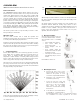
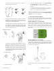
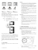


Table Of Contents

UTC. All Rights Reserved. 3 P/N 0000000 – Rev. A – 06 Nov 12
Jumper Adjustment (1) – switch settings.
There are three (3) jumpers switches located on the Printed Circuit
Board in the upper left corner. These jumpers assist in setup the device
and its operation. Jumper Switch definitions:
Input – reserved for future features – not used.
Walk Test – used to disable the wireless alarm to the control
panel. Default is OFF.
Pulse – selects the PIR sensitivity. Default is 100 lb pet
immunity.
Product shipped with factory default settings.
To verify the device detects all the areas, set the Walk Test jumper to
the ON position. This allows you to walk in all areas of coverage to
ensure the device detects a person’s movement. Make mechanical
mounting adjustments as required to cover the open area.
Depending on the pets inside the house, the motion detector’s Pet
Immunity is adjustable between 50 lbs or 100 lbs. Move the Pulse
jumper to pulse count 2-position for 50 lbs and pulse count 4 for 100
lbs.
5. Basic Operations
This detector is equipped with a learn-mode at startup and an intuitive
normal mode.
Power ON
o The detector turns on with a 3V battery on the board. Remove
the battery pull tab and/or ensure the battery is installed per the
plus and minus signs located on the PCB white legend.
o At power up, the detector’s Status LED blinks for 60 seconds
with 1Hz frequency or 60 times. During this time, learn mode,
the detector sets its internal parameters according to
surrounding environment.
o RF Status LED blinks 3 times, once per second and waits for next
2 seconds. This indicates the detector is looking for control
panel to pair with i.e. enrollment.
o The RF Status LED turns OFF after 2 minutes or after enrolling
with a control panel.
o If the battery is removed after enrollment into a control panel,
this enrollment sequence is skipped at the next power up. The
detector is already enrolled.
Normal Mode
o In normal mode of operation the Status LED remains OFF and
PIR sensor remains in power saving mode which increases the
battery life.
o The Sensor wakes upon the motion detection in the field of view
and the algorithm starts analyzing the signature of the heat
source movement.
o Once motion is detected in the field of view, the PIR status LED
turns ON for 2 seconds and sends the alarm signal to the
control panel using wireless message(s).
o Status LED remains ON as long as motion is detected in field of
view.
o Status LED turns OFF after two seconds when motion in no
longer detected in the field of view.
6. Installing / Replacing Battery
This detector comes with one battery preinstalled. When you need to
replace the battery, use the following procedure. Be sure the device is
mounted to the wall and the cover is attached before performing this
procedure.
o Place the control panel into sensor test mode. Otherwise, an
alarm/tamper condition may be indicated.
o Remove the top cover body off the detector.
o Remove the old battery and dispose of it properly, as
recommended by the battery manufacturer.
o Install the new battery. Note the polarity shown in the battery
compartment.
o Install the top cover onto the detector.
o Perform a sensor/RF test with the control panel. See “Error!
Reference source not found.
”.
Input
Opt 2
Opt 1
(default)
Walk Te s t
ON
OFF
(default)
Pulse
CNT 2
CNT 4
(default)
+
-